OBDX Development - Developer Tools and Suggestions

Programs / Tools / Scripts
User avatar
Tazzi
Posts: 3421
Joined: Thu May 17, 2012 8:53 pm
cars: VE SS Ute
Location: WA
Contact:

Re: OBDX Development - Developer Tools and Suggestions

Post by Tazzi »

hjtrbo wrote:For what its worth the HP Tuners MPVI2 drained my VF battery in 2 weeks.
I would doubt they implemented a power saver mode, I believe they support BLE which literally has the words "Low Energy" in the title, so they wouldnt draw as much current as the GT would most likely. If I disabled WIFI, this would probably drop currently quite a bit.

On a slightly different subject, I have finally wired up a Chrysler GPEC ECU which is 29bit based to ensure 29bit compliancy is done correctly.
The default header should be 18 DB 33 F1
And typical ECU response will be 18 DA F1 10

I did not actually have the correct default header and filter set for 29bit so the GT did not deal with that correctly.
Its amazing how little this is documented, I only found this going back through the SAE ISO 15765-4 documentation.
Your Local Aussie Reverse Engineer
Contact for Software/Hardware development and Reverse Engineering
Site:https://www.envyouscustoms.com
Mob:+61406 140 726
Image
kur4o
Posts: 946
Joined: Sun Apr 10, 2016 9:20 pm

Re: OBDX Development - Developer Tools and Suggestions

Post by kur4o »

https://github.com/commaai/opendbc

Some open info about CAN decoding used on various manufacturer.
User avatar
Tazzi
Posts: 3421
Joined: Thu May 17, 2012 8:53 pm
cars: VE SS Ute
Location: WA
Contact:

Re: OBDX Development - Developer Tools and Suggestions

Post by Tazzi »

kur4o wrote:https://github.com/commaai/opendbc

Some open info about CAN decoding used on various manufacturer.
Interesting, looks like that can be used to simulate a whole vehicle!

29bit CAN is working flawlessly. Its nice to see this works work something other then GM also. First time actually getting the Chrysler stuff on the bench.
CAN29bitWorking.PNG
CAN29bitWorking.PNG (2.1 KiB) Viewed 3818 times
The ELM auto protocol (AT SP 0) also works with this, its able to search through the protocols until it gets to the 29bit 500kpbs protocol and find the GPEC2 ECU. Considering how overly complex that routine is.. Im very happy with it.
Your Local Aussie Reverse Engineer
Contact for Software/Hardware development and Reverse Engineering
Site:https://www.envyouscustoms.com
Mob:+61406 140 726
Image
kur4o
Posts: 946
Joined: Sun Apr 10, 2016 9:20 pm

Re: OBDX Development - Developer Tools and Suggestions

Post by kur4o »

What I figured about CAn 29bit and 11bit is that the first 2 bytes are 00s on 11 bit and cut from tool to pc, but I are still send on bus, and 29 bit using full 4 bytes as header. It is claimed they are converted to decimal for meaning, but on some cases I can clearly see the individual bytes are encoded with some meaning.

Why don`t you listen for sleep command from power master bus module, and than when sensed put in low power mode. Waking up will need to be more creative.
User avatar
Tazzi
Posts: 3421
Joined: Thu May 17, 2012 8:53 pm
cars: VE SS Ute
Location: WA
Contact:

Re: OBDX Development - Developer Tools and Suggestions

Post by Tazzi »

kur4o wrote:What I figured about CAn 29bit and 11bit is that the first 2 bytes are 00s on 11 bit and cut from tool to pc, but I are still send on bus, and 29 bit using full 4 bytes as header. It is claimed they are converted to decimal for meaning, but on some cases I can clearly see the individual bytes are encoded with some meaning.

Why don`t you listen for sleep command from power master bus module, and than when sensed put in low power mode. Waking up will need to be more creative.
There does appear to be a difference for CAN29 and 11bit. If I setup an ELM cable to monitor the bus and only look for 11bit frames (0 to 0x7FF), and then using a different cable, send a 29bit frame with a header of 00 00 02 11, the ELM cable setup for 11bit does not see this frame. This could be an ELM only phenomenon, but maybe it does send an 11bit and 29bit header differently.

For power saving, this could be done if looking on GMs Global A vehicles since they all share the same wake/sleep commands. But as the tool is designed for more then just global A, it becomes near impossibly to find the wake/sleep commands in every single vehicle variant.

I had a little bit of success with having the tool go to sleep after detecting no more data from the car or connected application. It did go to sleep... but.. I then had issues getting the CAN interrupt back up and running... so todays fun filled job is dumping various registers to identify what changes once put into a low power mode. :roll:
Your Local Aussie Reverse Engineer
Contact for Software/Hardware development and Reverse Engineering
Site:https://www.envyouscustoms.com
Mob:+61406 140 726
Image
User avatar
Tazzi
Posts: 3421
Joined: Thu May 17, 2012 8:53 pm
cars: VE SS Ute
Location: WA
Contact:

Re: OBDX Development - Developer Tools and Suggestions

Post by Tazzi »

We currently have allocated some emulated eeprom space. Its flash space being used like an eeprom.
Now, theres quite a bit of space left in there. We have been approached by a few devs now asking about how they can tie a cable to their software. I have explained that each cable has its own unique serial which can be used to license their applications to so a license follows the cable (Which is what I do). But the latest individual has explained they want to mitigate someone cracking a software by actually 'locking' the cable so it can only be used once a special unlock routine is run.

They sell softwares that do various custom actions for a variety of manufactures (immo,key, ect) and have had issues with people cracking and onselling. Their thought process is, even if an eager cracker broke their software, it is still useless without the key to unlock the cable. Ontop of that, if it was to be cracked after a single cable has been licensed, the 'key' is valid only for that cable. If the seed/key calculation is never exposed in the application, then it will be much harder to work out.

So.. this is a very unique request that I think is actually possible! My train of thought is:
1) All ELM functionality is never affected and will always work
2) Only DVI command set is affected.
3) The Dev can assign a unique salt that will then generate a custom 'seed/key' based on that salt and unique serial
4) Once assigned, the DVI command set goes into a lockdown and does not operate until the seed/key process is completed.
5) To protect against reverse engineering dev software, the key can be calculated on a sever using basic PHP script

As I would never want someone to be held hostage by a dev if they bought a cable from them and they locked them out permanently, I would have a software that could wipe away the lock so its back to normal usage.

Its certainly a unique thought process on it. As a software dev, I would have jumped at the chance to use something like that back in the day.
Your Local Aussie Reverse Engineer
Contact for Software/Hardware development and Reverse Engineering
Site:https://www.envyouscustoms.com
Mob:+61406 140 726
Image
User avatar
Tazzi
Posts: 3421
Joined: Thu May 17, 2012 8:53 pm
cars: VE SS Ute
Location: WA
Contact:

Re: OBDX Development - Developer Tools and Suggestions

Post by Tazzi »

As much as I tried, I could not fit the above dev lock in so that will not be part of the GT release.
The core of the coding has been completed, but its implementation will have to wait until we either move to a larger chipset or newer device later down the road.

We now have our first batch of GTs which I have assembled and tested. Its only a small batch of 30, but something is better then nothing.
While majority of these are on the way to the United States, I will finalize the developers reference manual along with the GT J2534 API installer.

We already have another new prototype we are looking at which has triple CAN built into the chip set and ~3x memory/ram. This would open the capabilities to having HSCAN,MSCAN and GMLAN all on one chipset without any relay (Since those are bulky!). Along with fitting our next lot of protocols including J1850 PWM and kline, which would the the final 'major' OBD2 protocols. This will likely be the scantool we call "OBDX One" since we want it to have everything.

There shouldn't be alot more updates regarding scantools anymore, other then possibly FDCAN once an E99 ecu arrives. But the next fun begins with software development. A common question I get is reading GM based data/faults since alot of the free applications fail with GM specific faults and data. So Im thinking of effectively making a modern SOE application that should support all engine setups.
Your Local Aussie Reverse Engineer
Contact for Software/Hardware development and Reverse Engineering
Site:https://www.envyouscustoms.com
Mob:+61406 140 726
Image
User avatar
Tazzi
Posts: 3421
Joined: Thu May 17, 2012 8:53 pm
cars: VE SS Ute
Location: WA
Contact:

Re: OBDX Development - Developer Tools and Suggestions

Post by Tazzi »

Update time!

Making progress on the diagnostic application, currently dubbed as OBDXplorer.
Past week has been working out the layout of the program and the overall flow to ensure I do not end up with a major design flaw once beginning the core implementation.

Currently up to the following:
1) Majority of screens/design has been completed
2) OBDX Scantool auto detect and connection implemented, still need to do an auto detect ECU method.
3) Template class/function setup to deal with DPID implementation for both VPW and CANBus ecus.
4) Template screen for DTC fault reading and clearing - I would like to also implement Freeze data into this.

The data logging view has a few different screens to move between which include:
1) Dash - gauges and bars plus small graph view
2) Graph - Large graph with ability to enable/disable live data parameters (May configure to allow more then 1 graph)
3) List view - all data in a list, shows max and min values and can be setup to trigger coloured boxes depending on received value
4) Advanced 3 param graph logging - 2 parameters with fixed values are placed on X and Y, and the third (Z) axis is logged to the actual input cells.

Just found out the hard way, that there is a dedicated heat map that I could have used instead of trying to make a datagrid color format, so a bit of wasted time, but least this will work out much better and cleaner.

Todays job is completing the ECU auto detect routine and complete the following:
1) Get VIN
2) Get Serial
3) Get OS
4) Scan vehicle for supports PIDs - optional, can take a min or so depending on size of data list.
The last scan is optional, as the application will check against its local records if a vehicle with matching VIN/Serial/OS has already been connected before, and use that for its supported PID list 8-)

I then need to finish off the PID saving into either a JSON or XML format so they can be instantly imported into a full list. This will also be used for user defined parmeters which can be also be added manually. Ontop of that is finding a math parser which will deal with a multi bit encoded parameter to allow selecting different options per enabled bit. Some of these seem to accept a "if ((Y & bit)/(2^bit)) then blah elseif blah blah" statements, so this would allow isolating exact bits and rotating right to detect if 0 or 1.

Some PIDs like the Auxilary Inputs/Outputs are bit encoded with multiple different items, such as "Power take off output supported" and "Manual trans neutral gear supported" ect, so its basically like having multiple PIDs inside a single PID, these may need to be entered individually with the same PID value, but different calc to indicate the option. It will then be a matter of making sure the PID is not added twice to the DPID frame. If each of the gauges/displays are data bound to their respective PID object, then they should instantly update as soon as the received data bytes are parsed into the PID object and calculated (fingers crossed that works!).

So... lots to do! Hopefully no more then a couple weeks.
obdxplorer home screen.PNG
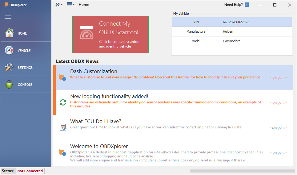
obdxplorer home screen.PNG (77.5 KiB) Viewed 3403 times
obdxplorer dashdisplay.PNG
obdxplorer dashdisplay.PNG (268.52 KiB) Viewed 3403 times
obdxplorer colourmap.PNG
obdxplorer colourmap.PNG (111.36 KiB) Viewed 3403 times
Your Local Aussie Reverse Engineer
Contact for Software/Hardware development and Reverse Engineering
Site:https://www.envyouscustoms.com
Mob:+61406 140 726
Image
MudDuck514
Posts: 397
Joined: Wed Jul 05, 2017 8:30 am
cars: 2001 Pontiac Grand AM SE
LD9 2.4l I4, 4T40E
2005 Chevrolet Venture
LA1 3400 V6, 4T65E
Location: North TX, USA

Re: OBDX Development - Developer Tools and Suggestions

Post by MudDuck514 »

Tazzi;

Awesome work as usual. My question at this time is what will this do that your SOE app does NOT do?

Mike
User avatar
Tazzi
Posts: 3421
Joined: Thu May 17, 2012 8:53 pm
cars: VE SS Ute
Location: WA
Contact:

Re: OBDX Development - Developer Tools and Suggestions

Post by Tazzi »

MudDuck514 wrote:Tazzi;

Awesome work as usual. My question at this time is what will this do that your SOE app does NOT do?

Mike
I wasn't 100% aiming for obdxplorer to be a dedicated logging tool for tuning, but, our current major user base is using the tool for tuning, so its kind of a priority at the moment. Eventually its going to be supporting other manufactures, but for now its a GM based app like SOE.

Things that obdxplorer will do that SOE doesnt:
1) Support alot more live data parameters (PIDs)
2) Include histogram support (Might not be in first revision, but I have started)
3) Include freeze data support (Might not be in first revision, but I have started)
4) OBDX tool specific support which means must faster logging.

After talking to some more tuners, I have also now decided that two different logging setups are required:
1) Basic View
2) Advanced View

Basic view is going to have all these menus/tables split up as per the design now, I find this setup is much less overwhelming for the average joe.
Whereas the advanced view is going to be just one screen which accepts docking in multiple displays. This will allow having dash, graph, histogram ect all on one display so it can all be monitored in one hit.

I have had experience with docking multiple displays into one screen, but have not had to pass lots of live data simultaneously between them all. So it is going to be interesting to see how I set that up, likely passing binding parameter/s on setup, that way updating the parameter in the main processing thread should automatically update all displays (Theoretically).

I am starting with the basic view first. Once I know that is working cleanly, I can then move to the advanced view.

Anyways, I got districted with the home screen designing yesterday, I spent way too long on trying to find something that I was happy with to display tool details and vehicle details, but believe I have finally got something Im happy with:
OBDX homescreen2.PNG
OBDX homescreen2.PNG (78.47 KiB) Viewed 3345 times
Your Local Aussie Reverse Engineer
Contact for Software/Hardware development and Reverse Engineering
Site:https://www.envyouscustoms.com
Mob:+61406 140 726
Image
Post Reply