USB BDM NT

They go by many names, P01, P59, VPW, '0411 etc. Also covering E38 and newer here.
User avatar
j_ds_au
Posts: 384
Joined: Sun Jan 25, 2015 4:21 pm
Location: Sydney

Re: USB BDM NT

Post by j_ds_au »

Gampy wrote:What BDM config is used for writing an Intel 1m chip??

ID'ing the chip always reports Unknown flash type, report these values to <bla bla bla> 89,889D.
Beware that ID'ing a memory chip (and further beware that not all types support this feature) typically involves applying 12V on address pin A9. So trying this in-circuit could blow up the micro if the circuit doesn't include protection measures for this situation.

Joe.
User avatar
j_ds_au
Posts: 384
Joined: Sun Jan 25, 2015 4:21 pm
Location: Sydney

Re: USB BDM NT

Post by j_ds_au »

DavidBraley wrote: I'm also reading that you can? and can't? (unable to find a definitive answer) program a parallel flash eeprom directly, like you would with an eeprom programmer, while it's pins are connected to a microprocessor. If anyone on this forum knows the answer, please chime in. I'm still very curious why the flash pins are accessible from the 90 pin header.
You can if :
1. Vpp (if used by the type of Flash chip) doesn't connect to something that won't like high voltage.
2. The micro is held in reset, and assuming this drives the Flash chip directly (not via buffers or gates).

Joe.
User avatar
DavidBraley
Posts: 172
Joined: Thu Jun 07, 2018 8:15 am
cars: 1948 GMC
Location: Fort Collins, Colorado

Re: USB BDM NT

Post by DavidBraley »

j_ds_au wrote:
DavidBraley wrote: I'm also reading that you can? and can't? (unable to find a definitive answer) program a parallel flash eeprom directly, like you would with an eeprom programmer, while it's pins are connected to a microprocessor. If anyone on this forum knows the answer, please chime in. I'm still very curious why the flash pins are accessible from the 90 pin header.
You can if :
1. Vpp (if used by the type of Flash chip) doesn't connect to something that won't like high voltage.
2. The micro is held in reset, and assuming this drives the Flash chip directly (not via buffers or gates).

Joe.
Thanks Joe!

My problem then would be finding the reset pin on the microprocessor. Datasheets don't help because GM had the manufacture change the pin locations at the time of packaging the die. Can you think of a way to find this pin? If we could find it (on any of these PCMs), it would mean there would be yet another way to read and write to the flash on these PCM's.

One thing I do know is it's safe to apply 12V to the Vpp pin on the Intel Flash found in the P01/P59 PCM. We do this now when using the BDM.

Thanks again for the input!
-David

I'm a machinist... because engineers need heroes too.
User avatar
j_ds_au
Posts: 384
Joined: Sun Jan 25, 2015 4:21 pm
Location: Sydney

Re: USB BDM NT

Post by j_ds_au »

DavidBraley wrote: My problem then would be finding the reset pin on the microprocessor. Datasheets don't help because GM had the manufacture change the pin locations at the time of packaging the die. Can you think of a way to find this pin? If we could find it (on any of these PCMs), it would mean there would be yet another way to read and write to the flash on these PCM's.
On older GM ECU/PCM's, they used a combined regulator and reset-generator chip, a SIP package attached to a heat sink. I'm guessing slightly younger ones may have the same arrangement. So it may be possible to identify this chip, then check which pin changes from high to low state when you create a "brown out" condition on the "12V" input. If this pin has a pull-up resistor, you can probably assume it has an open-collector output, which then means it would be safe to short this to ground to induce a reset condition. To be sure, you can use a mA meter to short this pin to ground, to confirm the current doesn't exceed expectations (per Ohm's law). You can further trace this to the MCU if you still want to know which pin it is there.

Joe.
User avatar
DavidBraley
Posts: 172
Joined: Thu Jun 07, 2018 8:15 am
cars: 1948 GMC
Location: Fort Collins, Colorado

Re: USB BDM NT

Post by DavidBraley »

j_ds_au wrote: On older GM ECU/PCM's, they used a combined regulator and reset-generator chip, a SIP package attached to a heat sink. I'm guessing slightly younger ones may have the same arrangement. So it may be possible to identify this chip, then check which pin changes from high to low state when you create a "brown out" condition on the "12V" input. If this pin has a pull-up resistor, you can probably assume it has an open-collector output, which then means it would be safe to short this to ground to induce a reset condition. To be sure, you can use a mA meter to short this pin to ground, to confirm the current doesn't exceed expectations (per Ohm's law). You can further trace this to the MCU if you still want to know which pin it is there.

Joe.
This is very helpful! It might even help me find the BDM pins on some of these other PCMs. The reset pin for sure. I'm going to further explore this...
-David

I'm a machinist... because engineers need heroes too.
User avatar
DavidBraley
Posts: 172
Joined: Thu Jun 07, 2018 8:15 am
cars: 1948 GMC
Location: Fort Collins, Colorado

Re: USB BDM NT

Post by DavidBraley »

Well, thanks to Joe, I have been able to find the reset pin on the V6 P04 and the inline 4 P08 PCMs. Of course, we have already known where it is on the P01/P59 PCMs.

So stepping off topic a little, this sets me up for experimenting with reading and writing to the flash ram on the PCM main board directly. My guts are telling me I should also try and put together some kind of bench simulator like what Gampy is working on. This would help me determine if the PCM has suffered any kind of damage from flashing the ram directly. We know flashing with the BDM, or through the OBD2 port using PCM Hammer works great. I will try flashing an 0411 first to see how it goes. I've got a few of these and can sacrifice one for a good cause. :lol:

I will do some experimenting and start a new thread. I'm just glad the BDM fixture I made is super universal. I should be able to direct flash the memory by just making a new probe pin head, and a custom cable that feeds to either my GQ 4x4 or XGecu Pro programmers. I have both on the bench...

Fingers Crossed!
-David

I'm a machinist... because engineers need heroes too.
In-Tech
Posts: 788
Joined: Mon Mar 09, 2020 4:35 pm
Location: California

Re: USB BDM NT

Post by In-Tech »

Hi David and all,

I received my USB BDM NT a few days ago and want to play with this dead p59 I have. I really like the jigs you and NSFW made and I hope to print one up soon. It's been so long since I did any jtag type stuff I have a couple questions to make sure I don't screw up.
BDM.jpg
BDM.jpg (11.57 KiB) Viewed 5222 times
Connection
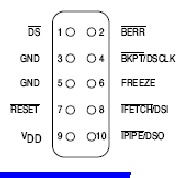
BDM connector of USB BDMNT NT ECU411
Pin 1 DS
Pin 2 BERR
Pin 3 GND
Pin 4 DSCLK
Pin 6 FREEZE
Pin 7 RESET
Pin 8 DSI
Pin 10 DSO
Connect WPP to 12V with 100ohm resitor. Make sure WPP is > 11.4V when power on.

Is pin 9(called vDD in drawing) used in this application on bdm?
Do you have power, ground and ign active with the blue PCM connector? I have an adjustable regulated power supply.
Do we just check the vpp(WPP in pics) pin on the flash to make sure it is 11.4-12.6v and if not we need to grab voltage from the power supply and resist it down(pot) to feed that pin? You mentioned a switch on this.
Do we use both pin 3 and pin 5 on bdm 10 pin connector to ground or is one enough?

>>>Bubba2533 wrote:
>>>"I carefully read through the datasheet this time and I found that I had the Vpp pin wired to +12v through a resistor (which is correct), but I didn't have RP# also wired >>>to +12v so it wouldn't let me write to the boot block."

Is this something I should look into doing or do we not need to write the boot block?

>>>NSFW wrote:
>>>And after setting up the flash chip in the USB-BDM app, I unbricked my AMD-based P59.
>>>Use the ECU4111M configuration file.
>>>Copy the NOR Flash configuration from the AMD AM29LV800BB chip, and just change the IDs to match for the AM29F800BB that's actually in the PCM (ID1 = 0001, ID2 = 2258).

I saw the screenshot antus posted and I'm a bit confused but maybe will be clear once I get started.

>>>David wrote:
>>>A big thanks to NSFW and i420tom! I got the BDM to correctly work with both the AMD flash AND the Intel flash P59's! I can read and write to both.

Did this take a custom xml file or ? What xml should I use? If there is anything else I am missing, I sure appreciate any guidance you all have.
User avatar
Gampy
Posts: 2333
Joined: Sat Dec 15, 2018 7:38 am

Re: USB BDM NT

Post by Gampy »

The following is my pinout description.
I have also PM'd you a Zip file called BDM Instructions and Pictures.zip that was created by 160plus (I believe) that I lightened by 87,681,705 bytes (103.9m->16.2m) simply by striping the Metadata from the images ... Hopefully, that does not offend him.

Pcm 90 pin header -> BDM
A-4 = GND -> Pin 3
A-7 = DS -> Pin 1
A-11 = DSI -> Pin 8
A-13 = DSO -> Pin 10

B-12 = BERR -> Pin 2

C-12 = RST -> Pin 7
C-29 = DSCLK -> Pin 4
C-30 = Freeze -> Pin 6

F1-20 = +12v
[edit] The following is one time configuration ...
When you open the BDM Software you will want to (if not already done),
Select: Tools
Select: Config
Select Category: Other
Select Protocol: BDM
Select Target Select: ECU4111M
Select: Ok

[edit] See Screenshots below ...
Select: Tools
Select: New Flash
Select: Nor Flash
This is where it gets tricky to write, What chip, Intel or AMD ... I'll example AMD ...
Select CopyFrom: AMD AM29LV800BB
Edit ID1: 01
Edit ID2: 2258
Edit Name: AMD AM29F800BB
Select: OK

For Intel (NOT AMD), I soldered a resistor to WPP(VPP) -> switch -> +12v at F1-20

Hopefully that answers all your Q's.

[edit]
Screenshots of the USB BDM NT Nor Flash dialog for the AMD and Intel 1m chips
AMD AM29F800BB Nor Flash dialog
USB_BDM_NT_NorFlash_Config_AMD-AM29F800BB.png (5.36 KiB) Viewed 5197 times
Intel AB28F800B5-B Nor Flash dialog
USB_BDM_NT_NorFlash_Config_Intel-AB28F800B5-B.png (5.43 KiB) Viewed 5197 times
Last edited by Gampy on Thu Apr 09, 2020 1:06 am, edited 9 times in total.
Intelligence is in the details!

It is easier not to learn bad habits, then it is to break them!

If I was here to win a popularity contest, their would be no point, so I wouldn't be here!
In-Tech
Posts: 788
Joined: Mon Mar 09, 2020 4:35 pm
Location: California

Re: USB BDM NT

Post by In-Tech »

Yes I think so, Thank You. The tip on the switch for WPP makes complete sense and critical. I'm going to try it out in a few hours. Time for some zzzz's for now :)
User avatar
Gampy
Posts: 2333
Joined: Sat Dec 15, 2018 7:38 am

Re: USB BDM NT

Post by Gampy »

I didn't do that at first, I just used an alligator clip on F1-20 ... That cost my heart a few years, it popped off mid write!

So I did the switch thing ...
I have since changed that as well, switch got in the way of the cover, so I soldered a alligator clip on a short wire to F1-20, I clip it to the resistor, now it clips solidly, I have it all shrouded in shrink tube, thus I can put the covers on and stack them.

I do leave the BDM header semi permanently installed on two of my bench pcms, an AMD 1m and Intel 1m.

If I need to BDM, I unstack (unless it's the top one), open the cover, plug in BDM, fix it, unplug BDM, re-cover, re-stack and back at it ...
Intelligence is in the details!

It is easier not to learn bad habits, then it is to break them!

If I was here to win a popularity contest, their would be no point, so I wouldn't be here!
Post Reply