Yup. I've had 5 designs built through them. Check their jscs website for part and package availability first if you want to have them do assembly. They have fairly limited selection. They will only do assembly on 1 side and SMT components knly, but the labor is very reasonable. Yheir turn around is quite quick for a 2 layer board (100mm x 100mm side restriction for $2/5 board deal). Shipping costs more than board itself haha. Still a great deal after. $20 shipped for 5 PCBs (no assembly).
I got my all pro boards on Wednesday when I placed my order last week.
ABS Hacking
-
jlvaldez
- Posts: 155
- Joined: Mon Feb 11, 2019 12:48 pm
- cars: '01 - Corvette Z06
'20 - Sierra Denali
'03 - Volvo S80 T6
'16 - Accord V6 - Location: DFW, Texas
Re: ABS Hacking
Did some more research. The Delivered Torque signal is a PWM signal. The EBCM provides a 12V pull up source and the PCM will ground it to create the PWM. 10% duty cyle is idle. 90% duty cycle is max torque. Not sure about the switching frequency for this one. If I assume it's the same as the request signal, then it's low.
The Requested Torque signal is also PWM. The PCM supplies a 5V pull up and the EBCM shorts it to ground to create a PWM signal. 90% duty cycle is no torque reduction request (normal driving). Anything under this (down to ~10%) is a request to reduce torque to the PCM.
According to the data manuals I have for diagnosing these signals, it claims the switching frequency is quite low, only ~120-135 Hz.
Also, I found out that there is a breakout tool that goes between the EBCM and the harness as a breakout harness. IE, I don't have to hack anything up. It's a Kent Moor J39700-300. I found one on fleabay for $22, so I snatched that up. Looks to be some parallel connector.
I'm going to redesign part of my board. The parts I really really really dont want to solder myself aren't in stock so I'm goign to swap to other components. Downside is they're bigger, and I think i'll need to drop my low pass filter for the analog signals... It should be ok, I hope.
The connector on the breakout harness looks to be some old 50 pin port. Not sure what. Parallel maybe? Some googling at old port picctures makes it look a lot like a 50 pin scsi connector... a CN50 is the name. Also referred to as SCSI-1.
Anyone with more experience with these older connectors can confirm? I think im going to hold off on sending my board to fab until I can confirm the pinout to the ABS connector. It would be super convenient if I could just use an extension cable for this thing and plug the breakout harness directly into my daughterboard and datalog
- Attachments
-
- connector.png (840.37 KiB) Viewed 2831 times
-
antus

- Site Admin
- Posts: 8250
- Joined: Sat Feb 28, 2009 8:34 pm
- cars: TX Gemini 2L Twincam
TX Gemini SR20 18psi
Datsun 1200 Ute
Subaru Blitzen '06 EZ30 4th gen, 3.0R Spec B - Contact:
Re: ABS Hacking
Yeah that looks like old school scsi, the technical name for the connector is Centronics 50
Something like this might save you some soldering. https://www.ebay.com.au/itm/SCSI-1-cabl ... 3672119488
Something like this might save you some soldering. https://www.ebay.com.au/itm/SCSI-1-cabl ... 3672119488
Have you read the FAQ? For lots of information and links to significant threads see here: http://pcmhacking.net/forums/viewtopic.php?f=7&t=1396
-
jlvaldez
- Posts: 155
- Joined: Mon Feb 11, 2019 12:48 pm
- cars: '01 - Corvette Z06
'20 - Sierra Denali
'03 - Volvo S80 T6
'16 - Accord V6 - Location: DFW, Texas
Re: ABS Hacking
Thanks for the confirmation. I've been looking for a PCB mount Centronics 50/CN50/SCSI-1 connector to throw on my board instead of the DB25 I have now. I would like to use the SCSI-2 connector, since it's just a smaller pitch and will likely fit. the DB25 was a bit too wide, not sure if I can comfortably fit the whole CN50 connector.
You can see below how honkin it is compared to the already large DB25 lmao. Hmmm...
I *can* make the board wider (i already had to expand it once to fit the op amps... It won't nicely fit on top of a RPi, but it shoudl fit on top. If I just go wider, I can fit the CN50 connector, which seems like a plus to me. Only thing I'm not sure about is how the hell I'd run a connector that big from the engine bay (where ECBM is) to the cabin... I still have to work on the vette this week. Tonight I finished installing fixed back seats and harnesses (I'm sick of of my street seats on track... I'm just caving it and calling it a 90% track only car now). I have a track event at COTA in Austin end of July, so I need to get her buttoned up and ready to go. If all goes well, maybe have a datalogger ready. I think that'll be a bit of a stretch though.
- Attachments
-
- bigconnector.png (63.47 KiB) Viewed 2828 times
-
MudDuck514
- Posts: 397
- Joined: Wed Jul 05, 2017 8:30 am
- cars: 2001 Pontiac Grand AM SE
LD9 2.4l I4, 4T40E
2005 Chevrolet Venture
LA1 3400 V6, 4T65E - Location: North TX, USA
Re: ABS Hacking
Hi all,
Back in the day, there were cables that had the Centronics 50 connector on one end and a DB25 connector on the other.
You MAY be able to wire up something similar to allow you to use your board as-is.
Mike
P.S. I found this, hope it helps:http://www.connectworld.net/scsi.html
Back in the day, there were cables that had the Centronics 50 connector on one end and a DB25 connector on the other.
You MAY be able to wire up something similar to allow you to use your board as-is.
Mike
P.S. I found this, hope it helps:http://www.connectworld.net/scsi.html
Last edited by MudDuck514 on Tue Jul 14, 2020 6:11 am, edited 1 time in total.
-
jlvaldez
- Posts: 155
- Joined: Mon Feb 11, 2019 12:48 pm
- cars: '01 - Corvette Z06
'20 - Sierra Denali
'03 - Volvo S80 T6
'16 - Accord V6 - Location: DFW, Texas
Re: ABS Hacking
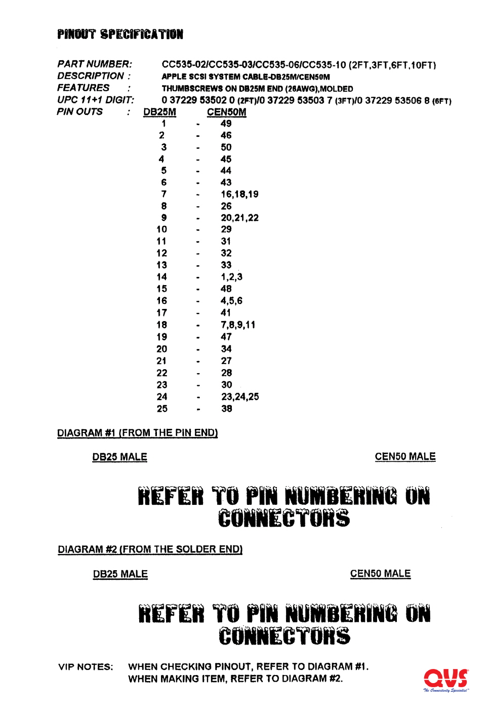
That's a good thought. I saw the CN50 to DB25 cables. I need to verify the pinout of the breakout cable and I cannot find any info online. So I'm going to sit here with a multi meter and continuity check when it comes in. Then I have to see which pins of the CN50 side are dropped to fit into the db25.
Either way, I need to check pinout of this breakout cable before I feel comfortable sending my analog board off to fab. I'll just wait and check and try to do this in 1 go. Those reluctor sensor front ends are almost $5/ea! And with the redesign I have to do, I'll need 4 of them
Either way, I need to check pinout of this breakout cable before I feel comfortable sending my analog board off to fab. I'll just wait and check and try to do this in 1 go. Those reluctor sensor front ends are almost $5/ea! And with the redesign I have to do, I'll need 4 of them

Re: ABS Hacking
Perhaps this is the info you're after :jlvaldez wrote:That's a good thought. I saw the CN50 to DB25 cables. I need to verify the pinout of the breakout cable and I cannot find any info online. So I'm going to sit here with a multi meter and continuity check when it comes in. Then I have to see which pins of the CN50 side are dropped to fit into the db25.
Either way, I need to check pinout of this breakout cable before I feel comfortable sending my analog board off to fab. I'll just wait and check and try to do this in 1 go. Those reluctor sensor front ends are almost $5/ea! And with the redesign I have to do, I'll need 4 of them
http://s505763140.onlinehome.us/specs/CC535-xx_S.jpg
mod edit: added the image locally as a backup
Joe.
- Attachments
-
-
jlvaldez
- Posts: 155
- Joined: Mon Feb 11, 2019 12:48 pm
- cars: '01 - Corvette Z06
'20 - Sierra Denali
'03 - Volvo S80 T6
'16 - Accord V6 - Location: DFW, Texas
Re: ABS Hacking
That sure is one part of the puzzle! Thanks.
I was trying to find out what ABS module pin goes to which pin on the CN50 as well. I think I'm just going to have to do a multimeter test for that. Couldn't find any info regarding the pinout for the J tool.
The harnesses should be delivered Thursday or Friday so I will hopefully have everything squared up this weekend and ready to send off to fab.
-
jlvaldez
- Posts: 155
- Joined: Mon Feb 11, 2019 12:48 pm
- cars: '01 - Corvette Z06
'20 - Sierra Denali
'03 - Volvo S80 T6
'16 - Accord V6 - Location: DFW, Texas
Re: ABS Hacking
I went to MSRC in Cresson today to get the Vette aligned and drove on track a bit to check my cooling mods for COTA in Austin next weekend. I also got a C5 and C6 ABS module from Louis as well as a partial harness.
Also got my ABS module breakout harnesses today. I'm going to probe them and start building a pinout.
I've got some bad news, mainly for me, is that my data server caught fire this morning. My 48 TB array seems intact but it fried my OS drive so I'm missing all my diagrams. This might cause some delay as I need to bring my server back online, and a lot of my custom stuff was for the OS hadn't been backed up fully yet.
So if any of you have the molded Molex to SATA power connectors, toss them in the trash. This is apparently a common issue when googling. I've ordered proper adapters but hope this is the only damage to my machine. I've got an off-site backup of all my data but it's in Houston at my dad's lol. Would take too long to transfer ~30 TB of data over the internet.
- Attachments
-
-
-
jlvaldez
- Posts: 155
- Joined: Mon Feb 11, 2019 12:48 pm
- cars: '01 - Corvette Z06
'20 - Sierra Denali
'03 - Volvo S80 T6
'16 - Accord V6 - Location: DFW, Texas
Re: ABS Hacking
Alright, I've continuity checked the harness. Not too bad. Below is the EBCM pin in the harness/connector side to the CN50 connector. Male and female connectors will have th ecorrect pin numbers, so it does't matter if male or female. I then labeled the function and the circuit number (if you look at the pictures a few pages back, you'll see them. Now to look at my layout since i can't do anything on my server right now (new SSD is on the way). What's interesting is that there is a steering wheel sensor signal that goes to the suspension control module, if you have one. Strange.
EBCM Pin (Connector??) CN50 Female Function Wire Color (Car) Circuit No.
G 19 Ground BLK 1250
F 43 Ground BLK/WHT 1251
E 18 Not Used
D 42 Variable Effort Steering Actuator Low Effort Control WHT 345
C 17 Variable Effort Steering Actuator High Effort Control GRY 1787
B 41 Ignition 3 Voltage BRN 641
A 16 Battery Positive RED 1642
1 26 Not Used
2 2 Delivered Torque TAN/BLK 464
3 27 Steering Wheel Position A LT GRN 1763
4 3 Not Used
5 28 Lateral Accelerometer Input (JL4) LT GRN/BLK 1338
6 4 Stop Lamp Supply Voltage LT BLU 20
7 29 Not Used
8 5 Left Rear Wheel SS Low Reference RED 885
9 30 Rear Rear Wheel SS Signal BRN 882
10 6 Right Front Wheel SS Signal DK GRN 872
11 31 Left Front Wheel SS Signal LT BLU 830
12 7 Requested Torque Signal ORN/BLK 463
13 32 Low Reference ORN/BLK 556
14 8 Not Used
15 33 Not Used
16 9 Not Used
17 34 Brake Pressure Sensor Signal (JL4) BLK 2626
18 10 Steering Wheel Position Signal B LT BLU 1764
19 35 Yaw Rate Sensor Signal (JL4) DK BLU 716
20 11 Not Used
21 36 ABS/TCS Class 2 Serial Data LT BLU 1122
22 12 Left Rear Wheel SS Signal BLK 884
23 37 Rear Rear Wheel SS Low Reference WHT 883
24 13 Rear Front Wheel SS Low Reference TAN 833
25 38 Left Front Wheel SS Low Reference YEL 873
26 14 Not Used
27 39 Steering Wheel Position Sensor 5V Reference Voltage GRY 1056
28 15 Steering Position Sensor Signal (Output to Electronic suspension control module) LT Blue 2627
29 40 Not Used