Creating a camshaft signal
Creating a camshaft signal
Working on making a circuit to create a cam signal, using the crank shaft signal for bench testing PCMs. Would this circuit work? Circuit is based on SN74HC163 chip. Not sure if that is the best one to use or not.
- Attachments
-
- cam_sig_circuit.png (37.86 KiB) Viewed 2969 times
-
MudDuck514
- Posts: 397
- Joined: Wed Jul 05, 2017 8:30 am
- cars: 2001 Pontiac Grand AM SE
LD9 2.4l I4, 4T40E
2005 Chevrolet Venture
LA1 3400 V6, 4T65E - Location: North TX, USA
Re: Creating a camshaft signal
Hi all,
Just a quick observation - IF you are wanting to create a "4x" cam signal, the circuit shown will not do it as the Q outputs do not change sequentially like a decade counter would (IE a 4017).
The Q output will remain in an "active" state as long as the bit is needed to count eg the Qc output wiill remain active from a count of 4 until a count of 8 at which time Qd becomes active.
It will again become active at a count of 12 until 15.
Mike
-
Holden202T

- Posts: 10311
- Joined: Sat Feb 28, 2009 9:05 pm
- Location: Tenambit, NSW
- Contact:
Re: Creating a camshaft signal
which would probably be perfect for an LSx 50/50 on/off signal ?
No matter what the question is, the answer is always more horsepower! 
Just starting out? Have a read of the getting started guide
Basic tuning of a delco ECM with $12P thread
Advanced tuning of a delco ECM with $12P thread
Just starting out? Have a read of the getting started guide
Basic tuning of a delco ECM with $12P thread
Advanced tuning of a delco ECM with $12P thread

Re: Creating a camshaft signal
You need to tie the ENP, ENT and /LOAD pins high. You should also tie the A, B, C and D pins either high or low.
Joe.
Joe.
Re: Creating a camshaft signal
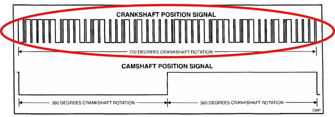
The goal is to create a 4x / 1x, crank / cam compatible signal to feed into an LS PCM.
For the ENP, ENT, Load, can I just directly hook them to 5 volts? Same question for the A, B, C and D pins. Straight to ground? I have seen some circuits that put in like a 1k resistor.
For the ENP, ENT, Load, can I just directly hook them to 5 volts? Same question for the A, B, C and D pins. Straight to ground? I have seen some circuits that put in like a 1k resistor.
-
jlvaldez
- Posts: 155
- Joined: Mon Feb 11, 2019 12:48 pm
- cars: '01 - Corvette Z06
'20 - Sierra Denali
'03 - Volvo S80 T6
'16 - Accord V6 - Location: DFW, Texas
Re: Creating a camshaft signal
To be honest I'm not sure how it creates a 24x crank and a 1x cam signal that works from one single chip but regarding the inputs, they're just CMOS inputs. So you it doesn't matter if you short them to 5v or use a resistor. Makes no difference. Typically I use resistors because they're easier to blue wire it I screw something up. That's for a PCB though. If you're bread boarding it, just short it directly.
Note that a 24x crank signal is not a simple 50/50 square wave.
Note that a 24x crank signal is not a simple 50/50 square wave.
Re: Creating a camshaft signal
Yes, I understand what the 24x signal looks like. That is why I am trying to keep it simple and just do the 4x stuff.
-
jlvaldez
- Posts: 155
- Joined: Mon Feb 11, 2019 12:48 pm
- cars: '01 - Corvette Z06
'20 - Sierra Denali
'03 - Volvo S80 T6
'16 - Accord V6 - Location: DFW, Texas
Re: Creating a camshaft signal
Sorry, I misunderstood then.
In that case, yes. Refer to my above note. You can short to supply or gnd or use a resistor. It doesn't matter at all. A CMOS input is a high impedance input, and needs virtually 0 current to detect a high or low threshold.
In that case, yes. Refer to my above note. You can short to supply or gnd or use a resistor. It doesn't matter at all. A CMOS input is a high impedance input, and needs virtually 0 current to detect a high or low threshold.
Re: Creating a camshaft signal
In the very, very old days of the original TTL logic parts, the inputs were NPN emitters which had a very limited breakdown voltage, typically less than the breakdown voltage of the power supply pin. So to tie these inputs high, series resistors were used to protect them from small voltage transients which may exist on the power supply rail and so exceed their breakdown voltage.
With the advent of LS-TTL, almost all these parts used diodes for their inputs (so were really DTL rather than TTL), and as the diodes had a much higher breakdown voltage than did transistor emitters, the need for series resistors to tie inputs high actually disappeared.
Similarly with CMOS parts, the MOSFET gate inputs have a higher breakdown voltage than the power supply pin (and almost all have a clamping diode to the power supply pin anyway), so again, no need for a series resistor to tie these inputs high.
Sometimes series resistors can be seen used to tie inputs high with modern logic parts, but that is just a throwback to the TTL designs of old, where this practice has been copied without understanding the former reason for doing so.
Joe.