Page 17 of 17
Re: ALDL LCD Display
Posted: Tue Feb 11, 2025 11:42 am
by BennVenn
Yeah, the source says its a 16bit value there. Let me know if it still doesn't work and i'll setup a bench 808
Re: ALDL LCD Display
Posted: Tue Feb 11, 2025 11:57 am
by Vrv8hz
Thanks

its switching now. But it's still displaying the headings from page 1. Do I need to insert a command to clear the screen between?
Edit: BLK=1 got it
Re: ALDL LCD Display
Posted: Tue Feb 11, 2025 2:59 pm
by BennVenn
if you position the gauges on window2 just right, you don't need to do the BLK=1, its a little smoother that way but good to see you got it running the way you want! You can also put text with just spaces to clear sections, again a little quicker but BLK works just fine too
Re: ALDL LCD Display
Posted: Wed Feb 19, 2025 7:51 am
by BennVenn
Another 10 added to the store if anyone is after one. A SD card and 3d printed enclosure is included
Re: ALDL LCD Display
Posted: Fri Feb 21, 2025 7:42 am
by Vrv8hz
BennVenn wrote: ↑Sat Nov 23, 2024 11:48 am
you would add something like this to the CONDITIONS{} area in the config file
IO1=VAR09>0BB8=00;
IO1=VAR09<0AF0=FF;
This is assuming RPM is assigned to VAR09 (in the math section)
IO1 output is set to 00 (0% duty cycle, or effectively off) when VAR09 (the RPM) is > (greater than) hex value 0BB8 (in decimal = 3000RPM)
it'll then check the next condition
IO1 output is set to FF (100% duty cycle, or ON) when VAR09 (the RPM) is < (less than) hex value 0AF0 (in decimal = 2800RPM)
so assuming you had IO1 going to a relay which is powering the ignition coil, if you go over 3000RPM it'll shut the relay off until RPM falls below 2800RPM.
You can also add more conditions after it, example
IO1=VAR02>00C8=00;
here, IO1 is turned off (0% duty) when VAR02 > 200KPA. Like a boost safety.
Every packet that is received from the ECU, all the conditions are checked once again, so it is the last valid condition that actually controls the IO.
This would always give you 2step which is probably not ideal. You could disable it with a rocker switch or push button, or I can update the code so you can assign a VAR with IO2's logic state. So you could check for a pushbutton press in the conditions, from IO2, and have that enable or disable the 2 step.
Sorry if this reads as a little complicated! Might be best to connect a test lamp / led to the IO1 output and try some code to see how it works, and if you need the IO2 as an input into a VARxx, I'll code that up
After fitting a stall to the TH400 yesterday I am interested in giving this a try.
What would the basic circuit to cut power to the coil after discharge look like?
I will be set it up with a test light first as you have advised, just want to know the direction I will be heading.
Re: ALDL LCD Display
Posted: Fri Feb 21, 2025 8:14 am
by BennVenn
At its simplest, you need to make sure EST is low before disabling it.
Re: ALDL LCD Display
Posted: Fri Mar 07, 2025 8:24 pm
by pcman
about to run wires in my l300 to wire in a pair of these, im running a vr v6 and auto 11p 424 ecu, the ecu is under my campervan conversion so need to run the wires to the dash, am I correct with these ecu connections? d3 - +5v, c11 - tx/rx, c2,3,13 - ground
does anyone have a 11p config file they can upload so i can be lazy, initially anyway
Re: ALDL LCD Display
Posted: Thu Mar 20, 2025 5:15 pm
by Muncie
I've been looking to make something similar to this for my VY...... without reading all 17 pages
Would this run on a vy flash pcm? Or could it be made to.??
Re: ALDL LCD Display
Posted: Wed May 14, 2025 7:49 am
by Vrv8hz
Regarding a simple circuit to interface from the display output to the ignition coil for 2 step. Does anyone want to give me some feedback on the circuit? I'm still at the point of trying to get it to work on the bench but having problems getting the NOR latch to work reliably. Could be needing resistors to stop it floating? I assume it will also require a SSR before the coil and maybe something to drive the SSR as well.
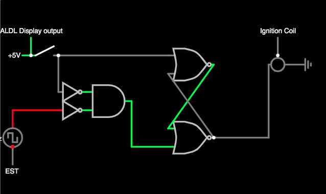
- Screen Shot 2025-05-14 at 7.43.42 am.png (33.46 KiB) Viewed 3089 times
Re: ALDL LCD Display
Posted: Wed May 14, 2025 10:26 am
by BennVenn
I'd suggest using dedicated flip flop IC's, rather that constructing them from individual gates, just for the edge sensitivity which will be helpful here. When i get a minute i'll draw something up.
 its switching now. But it's still displaying the headings from page 1. Do I need to insert a command to clear the screen between?