
you have to remember though, you forcing air in the inlet pipe is very different to pistons sucking air in through that same inlet tract from the other end of the system.
I don't doubt the difference in distribution you saw just that to really test it properly I think you need to measure from a suction point of view .... but that's hard to do on the whole system as it normally works.... ie. each cylinder opening in order and adding its pulses to the inlet manifold....
Fins on back of Valve & Fins pre TB
-
Holden202T

- Posts: 10435
- Joined: Sat Feb 28, 2009 11:05 am
- Location: Tenambit, NSW
Re: Fins on back of Valve & Fins pre TB
No matter what the question is, the answer is always more horsepower! 
Just starting out? Have a read of the getting started guide
Basic tuning of a delco ECM with $12P thread
Advanced tuning of a delco ECM with $12P thread
Just starting out? Have a read of the getting started guide
Basic tuning of a delco ECM with $12P thread
Advanced tuning of a delco ECM with $12P thread
-
immortality
- Posts: 3820
- Joined: Thu Apr 09, 2009 2:31 am
- cars: VS,VT,VX,VE
Re: Fins on back of Valve & Fins pre TB
Next time it's on the dyno, use a infra-red heat gun to measure the temps of each exhaust port just after the exhaust manifold flange. A difference in temps will indicate different mixtures.
-
delcowizzid

- Posts: 5709
- Joined: Sat Feb 28, 2009 10:38 am
- Yahoo Messenger: [email protected]
- Location: Wellington NZ
Re: Fins on back of Valve & Fins pre TB
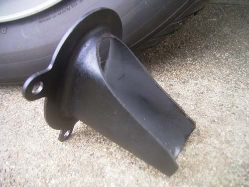
the bellmouth helped low throttle low rpm distribution didnt help WOT distribution just swaps the leaness from back to front LOL.people have cut the top out the bellmouth years ago so its like a tray with sides to get even better distribution and more flow.i can tell you the elbow is a restriction so is the manifold ive flowed both on a head and get about 1 inch of vacum from fitting the manifold with elbow half as much just the manifold itself.series 1 manifold has the runners way down in the bottom of the plenum and is probably better for more even distribution series 2 the runner are at the top of the plenum with air blasting past the ends of the ports.we havnt seen any distribution issues wih series 1 manifold at 450rwhp all plugs the same colour untill we got up over 30psi and the exhaust manifolds started flowing different side to side leaned one side a little or it could of been the fuel rail running out of flow to the 2nd half LOL
If Its Got Gas Or Ass Count Me In.if it cant be fixed with a hammer you have an electrical problem
-
vlad01

- Posts: 8550
- Joined: Mon Oct 08, 2012 8:41 am
- cars: VP I S
VP I executive
VP II executive
VP II executive #2 - Location: Kyneton, Vic
Re: Fins on back of Valve & Fins pre TB
yeah Im aware of that. I did mention it wouldn't be quite the same as the engine drawing in rather it being fed in.Holden202T wrote:you have to remember though, you forcing air in the inlet pipe is very different to pistons sucking air in through that same inlet tract from the other end of the system.
I don't doubt the difference in distribution you saw just that to really test it properly I think you need to measure from a suction point of view .... but that's hard to do on the whole system as it normally works.... ie. each cylinder opening in order and adding its pulses to the inlet manifold....
Interestingly if I do this same thing to an ecotec manifold, each port flows out the same for or less despite coming in from one side. I do believe the air tumbles in the plenum as 2 vortices
-
vlad01
- Posts: 8550
- Joined: Mon Oct 08, 2012 8:41 am
- cars: VP I S
VP I executive
VP II executive
VP II executive #2 - Location: Kyneton, Vic
Re: Fins on back of Valve & Fins pre TB
thats a good idea. might try thatimmortality wrote:Next time it's on the dyno, use a infra-red heat gun to measure the temps of each exhaust port just after the exhaust manifold flange. A difference in temps will indicate different mixtures.
-
immortality
- Posts: 3820
- Joined: Thu Apr 09, 2009 2:31 am
- cars: VS,VT,VX,VE
Re: Fins on back of Valve & Fins pre TB
vlad01 wrote:thats a good idea. might try thatimmortality wrote:Next time it's on the dyno, use a infra-red heat gun to measure the temps of each exhaust port just after the exhaust manifold flange. A difference in temps will indicate different mixtures.
It's a good way to find a dodgy fuel injector too.
-
delcowizzid
- Posts: 5709
- Joined: Sat Feb 28, 2009 10:38 am
- Yahoo Messenger: [email protected]
- Location: Wellington NZ
Re: Fins on back of Valve & Fins pre TB
like this might be a good test on the dyno http://i66.photobucket.com/albums/h242/ ... lmouth.jpg
If Its Got Gas Or Ass Count Me In.if it cant be fixed with a hammer you have an electrical problem
-
TdracerTd

- Posts: 488
- Joined: Mon Aug 19, 2013 12:39 pm
- cars: Td Gemini coupe (race car WIP)
Holden VE SS ute (tow car/daily)
Vp commodore V6 (race car, s/c, e85, intercooled)
Jeep Grand Cherokee Overland (mrs car, family bus)
My12 subaru STi (Weekend warrior/Toy)
1972 LJ torana GTR (my Dad's car)
Mitsubishi Evo IX
Re: Fins on back of Valve & Fins pre TB
Or a bad plug.immortality wrote:vlad01 wrote:thats a good idea. might try thatimmortality wrote:Next time it's on the dyno, use a infra-red heat gun to measure the temps of each exhaust port just after the exhaust manifold flange. A difference in temps will indicate different mixtures.
It's a good way to find a dodgy fuel injector too.
Any progress. This subject interests me greatly.

-
vlad01
- Posts: 8550
- Joined: Mon Oct 08, 2012 8:41 am
- cars: VP I S
VP I executive
VP II executive
VP II executive #2 - Location: Kyneton, Vic
Re: Fins on back of Valve & Fins pre TB
I just got back from Sydney today, was working there all week and weekends. I haven't had any time to look into it more just yet.
-
VL400

- Posts: 4991
- Joined: Sun Mar 01, 2009 4:54 am
- cars: VL Calais and Toyota Landcruiser. Plus some toys :)
- Location: Perth, WA
Re: Fins on back of Valve & Fins pre TB
How about this for a custom intake manifold .. http://www.racecar-engineering.com/arti ... of-racing/
It would be done with a powder type 3D printer rather than the extrusion type.
It would be done with a powder type 3D printer rather than the extrusion type.