Page 3 of 16
Re: Delco DIS On Non DIS Enigine
Posted: Sat Aug 28, 2010 7:29 pm
by VL400
BradGTV wrote:has anyone tryed attaching a crank trigger to a grinder, lathe or similar so it turns. then having the crank trigger mounted near it. then have power/earth onto the ingnition module and the crank sensor pluged in. then have 4 spark plugs with leads connected to the coils. would this set up produce a spark? (the ecu would not be connected) i have seen this test done using ford edis but wondering if i can do this with the delco. this way i can test cranks sensors until i get one that works.
I have a bench setup like this actually. Its a small frame with a 12V DC motor with a crank trigger mounted near the chopper wheel. Can also use a battery drill with variable speed, most will get at least 1000 rpm flatout. That EDIS setup throws out some spark power

Nice find on the Jackaroo too!
Re: Delco DIS On Non DIS Enigine
Posted: Sat Aug 28, 2010 8:58 pm
by BradGTV
cool, i will have to set one of these up shortly
iam know going to add the DIS (d1927a) module to the camira loom.
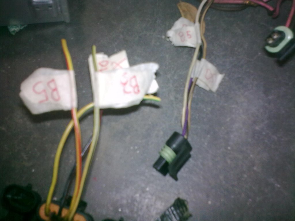
using the camira wiring diagram i have marked the wires which are required - D4,D5,B3,B5
and using the wiring diagram posted previously on this thread i have marked the wires on the DIS module plug.
the wires (d4,d5 ect..) on the camira loom go to the camira ignition module. so i basically need to cut the plug of and join the matchin wires to each other.
just to triple check is this what needs to be done? the pictures below show what i mean...
also, when the DIS coipacks are being used, the camira coil pack is obviusly not needed, so do i take these wires (from camira ignition module to coil pack and from coil pack to ecu) out of the loom altogether?
sorry if i sound a little simple

but im new to EFI and would rather not have to go buy another camira loom....
- join them like this?
- 28082010_013_sm.jpg (90.85 KiB) Viewed 13722 times

- is this what needs to happen?
- 28082010_011_sm.jpg (101.88 KiB) Viewed 13734 times
Re: Delco DIS On Non DIS Enigine
Posted: Sun Aug 29, 2010 12:55 pm
by VL400
Yeah just connect the EST of the module to the EST wire of the camira loom, Ref to ref, bypass to bypass etc etc. Leave a small amount of cable attached to the camira plugs and you can alway re-join if needed.
Re: Delco DIS On Non DIS Enigine
Posted: Wed Sep 01, 2010 3:21 pm
by Mechcano
BradGTV
For your Crankshaft position sensor you could use one from a 1999 Ford Ranger. Was the Crankshaft position sensor missing on the Jackaroo?
The 265 Hemi on the first page has a VR sensor that came from a Ford Ranger, part number FOEE 603 5-42B.
Use this link for a VR sensor from a US 1999 V6 Ranger (SU4101).
http://www.e-webcatalog.com/wells/PartF ... anuf_No=PA

Re: Delco DIS On Non DIS Enigine
Posted: Wed Oct 06, 2010 8:39 am
by BradGTV
thanks for the suggestion mechcano.
i went down to u-pull-it and got a abs sensor from a commodore so i will see if that works. i will be making a crankshaft pulley up on the lathe for the alfa, it will have a pulley for the water pump/alternator and crank trigger on it. just to make sure - the notch that is on top dead centre has to be on top dead centre of the engine?
also, does it matter what position the crank sesnor is mounted around the crank trigger wheel?
cheers, brad
Re: Delco DIS On Non DIS Enigine
Posted: Wed Oct 06, 2010 11:08 am
by Holden202T
the top dead centre mark can be anywhere you want, aslong as its pointing at the crank trigger when the motor is on TDC.
Re: Delco DIS On Non DIS Enigine
Posted: Wed Oct 06, 2010 4:44 pm
by Mechcano
Brad
"In a 4-cylinder application, the notches DO NOT coincide with TDC, except for the one at TDC for cylinder#1. The sync pulse comes at 70° after TDC for the #1 cylinder."
So the diagram below should show the relationship between the VR sensor and the trigger wheel when the engine is at TDC #1 cylinder. (note the vr sensor should be rotated 45deg anti clockwise)

- 4cyl_dis_ring2.gif (9.31 KiB) Viewed 13296 times
Below is an example of how it may look when mounted on the engine.
The VR sensor should be solidly mounted, the engine is at TDC #1 cylinder and the leading edge of the notch in the Trigger wheel at the centre of the VR sensor.
This will then have the sync pulse 70deg ATDC as in the above diagram.
Also try to keep the gap between the VR sensor and the Trigger wheel to 1mm or less.

- example2.jpg (61.14 KiB) Viewed 11652 times

Re: Delco DIS On Non DIS Enigine
Posted: Thu Oct 07, 2010 8:01 pm
by BradGTV
Thanks for help guys,
the diagram made things alot clearer!
tomorrow i will be putting my crank trigger wheel in my lathe, mounting the ABS sensor onto the tool post and firing some spark plugs using the coil packs and module, it will interesting to see if the ABS sensor and how the whole system will work.
thanks, Brad
Re: Delco DIS On Non DIS Enigine
Posted: Tue Feb 22, 2011 12:43 am
by antus
When setting up a 6 cyl dis system like this, whats the right reference degrees? Is it 10 like the reference notch or 60 like commodores?
Re: Delco DIS On Non DIS Enigine
Posted: Tue Feb 22, 2011 1:00 am
by VL400
Depends how you have it setup, if each notch is right on TDC and the notches are positioned like the last picture (the sync pulse happens 70deg ATDC #1) then it would be 60degrees. If your sync is on TDC #1 then it would be 10deg I think. After reading back a bit some sources put the notches 10deg BTDC of each cyl for cranking advance.