Page 1 of 16
Delco DIS On Non DIS Engine
Posted: Wed May 13, 2009 12:31 pm
by Apples
OK to go DFI you will need a module 4 cyl = D1927A or 6 cyl = D1928A
as pickup from a GM abs wheel sensor or similar.
make a trigger wheel by copying the picture below.
- Diswhl.gif (8.3 KiB) Viewed 29095 times
but you will have to get some commodore coils and wiring plugs to fit the module.
her is one of the required plugs
http://www.diyautotune.com/catalog/wire ... p-359.html
D1927A
http://cgi.ebay.com/ebaymotors/ws/eBayI ... OTORS:1123
D1928A
http://cgi.ebay.com/ebaymotors/ws/eBayI ... OTORS:1123
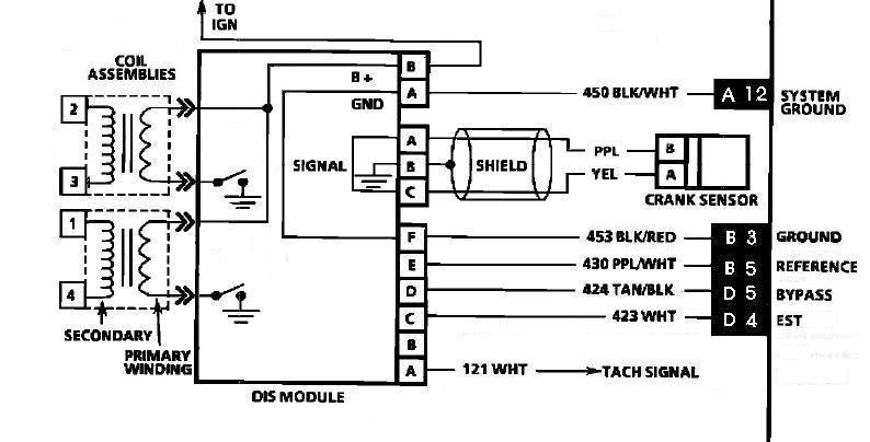
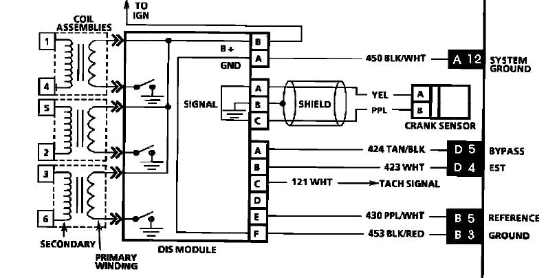
Wiring to 808
- 4cyl dis.JPG (49.56 KiB) Viewed 28570 times
- 6cyl dis.JPG (53.88 KiB) Viewed 29020 times
Hope this helps.
Changed 4 cyl dis picture to correct pin outs
blah
Posted: Wed May 13, 2009 8:18 pm
by wake77
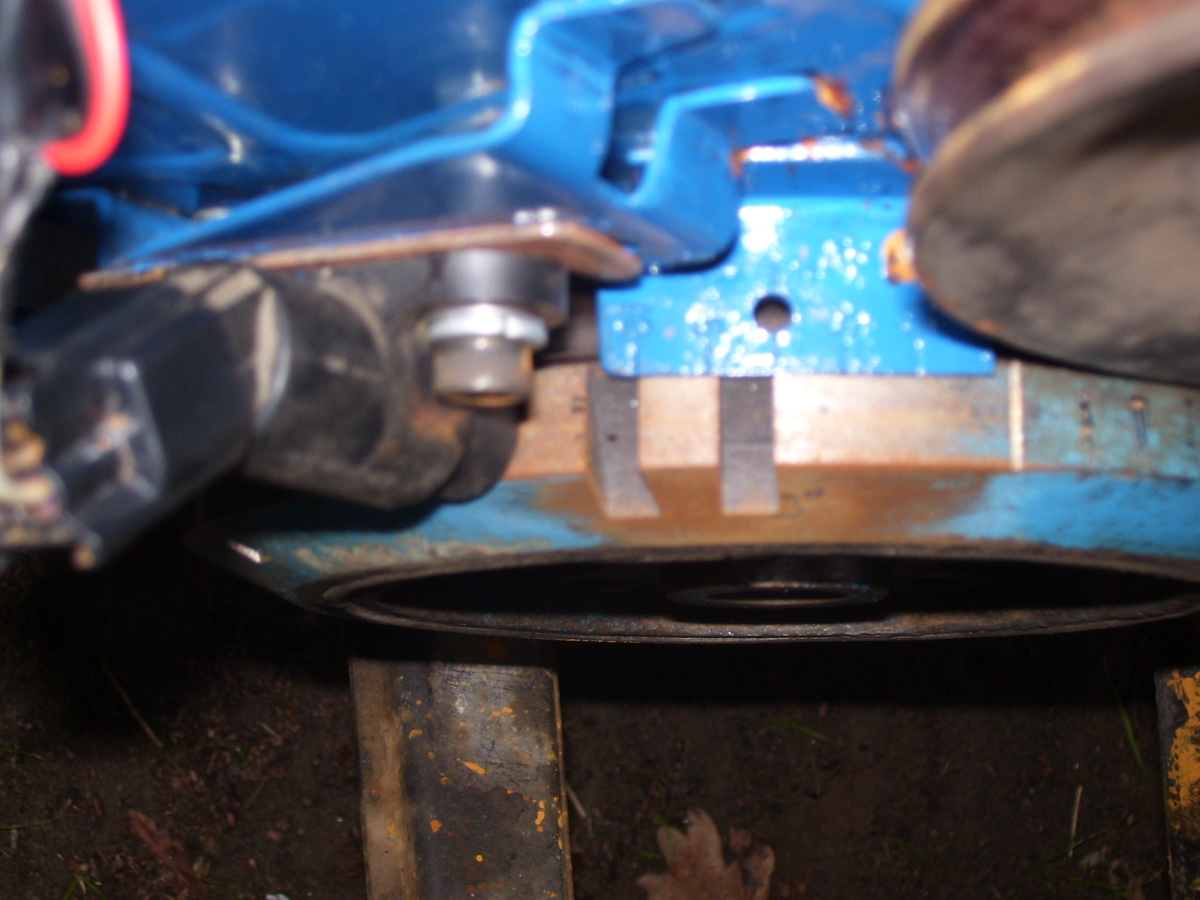
here are some pictures of the setup on the commodore
Re: 1UZ Toyota Ignition Conversion
Posted: Wed May 13, 2009 8:23 pm
by wake77
and some more details
Delco DIS On None DIS Enigine
Posted: Mon May 18, 2009 10:01 pm
by Apples
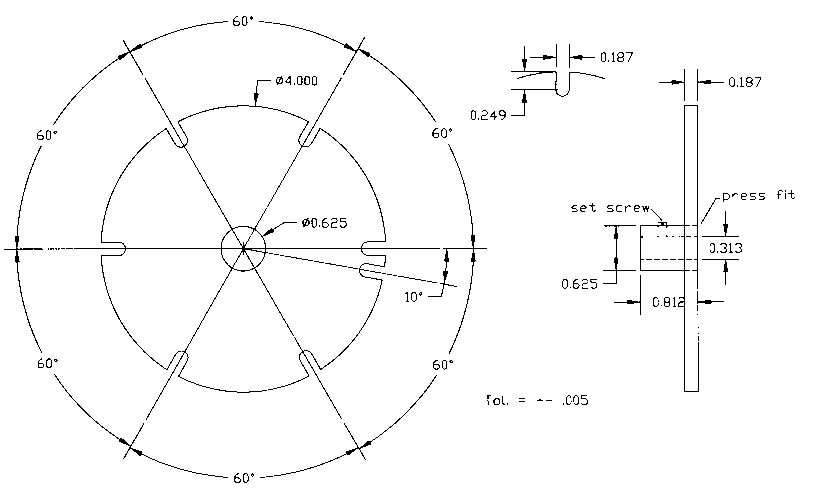
The trigger wheel picture above is more for making one the following one is the way it should be mounted for rotation.
Also more info here
http://www.megamanual.com/ms2/GM_DIS.htm
In a 4-cylinder application, the notches DO NOT coincide with TDC, except for the one at TDC for cylinder#1. The sync pulse comes at 70° after TDC for the #1 cylinder.
In a 6-cylinder application, the evenly spaced notches coincide with TDC. The sync pulse notch coincide with 10° after TDC for the #1 cylinder.
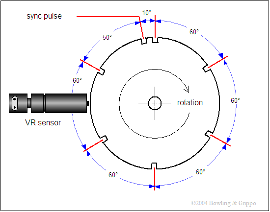
- dis_ring.gif (9.99 KiB) Viewed 28961 times
A Hemi 265 balancer made in to the trigger wheel
- trigger1.jpg (313.57 KiB) Viewed 28968 times
Re: Delco DIS On Non DIS Enigine
Posted: Mon Jun 08, 2009 12:20 pm
by VL400
Started drawing up a crank trigger for a 4cyl DIS (so the 7x crank pickup) and have some queries...
1) Which of the two pictures above is correct, one has a sync pulse before a ref pulse and one after? Apples mentioned the second picture is correct for the rotation, so after?
2) The statement from the megamanual page "In a 4-cylinder application, the notches DO NOT coincide with TDC, except for the one at TDC for cylinder#1. The sync pulse comes at 70° after TDC for the #1 cylinder." seems incorrect. How can some not coincide with TDC? They are 60deg apart and a 4 cyl fires every 180* of crank rotation, so two of them have to coincide with TDC of each cyl. Can anyone confirm the 70* ATDC of #1 for the sync pulse?
3) Am finding conflicting info as the wether the notches are right on TDC or 10* BTDC. I suspected they were 10* BTDC for the cranking spark advanced, but the reference angle for when the engine is running is 60deg not 70deg so that indicates they are right on TDC.
A factory trigger diagram would be most helpful!
Re: Delco DIS On Non DIS Enigine
Posted: Mon Jun 08, 2009 7:56 pm
by Apples
I have been unable to get factory info on the dis units I know that the last 4cyl I make two trigger wheels and if I remember correctly set engine up TDC number 1 cyl and set the offset by 70 deg made the trigger wheel spin on the crank shaft held tight by the balancer bolt.
adjusted till I got it to run correctly.
when it ran correctly I then make second trigger wheel bolt to balancer and made pickup mounting position where it fitted engine the best with correct relationship.
I had a look for my notes but can not locate them and unable to locate other things after moving house.
As long as the The sync pulse comes at 70° after TDC for cylinder #1 it should be correct for a 4cyl. sounds correct as per above link.
Please let me know it I am wrong as its been 2 years now from last time I played with it and last time I asked the owner its still going strong.
Re: Delco DIS On Non DIS Enigine
Posted: Mon Jun 08, 2009 8:38 pm
by VL400
Thanks Apples, might try and do the same to get it setup initially. I will be sure to post info up once I get something happening.
Re: Delco DIS On Non DIS Enigine
Posted: Mon Jun 08, 2009 10:30 pm
by antus
That top diagram shows on the first pic the center bit is 0.625, and from the other half, thats the back view not the front view. It doesnt show angle of rotation, so I think it actually matches the megasquirt docs when you consider it that way around. I wouldnt expect to the megasquirt docs to be wrong as they would be used on lots of 4 cyl cylinder cars and someone would have surely reported it by now.
Re: Delco DIS On Non DIS Enigine
Posted: Mon Jun 08, 2009 10:44 pm
by VL400
Good pickup Antus, I figured that was the reason but did not notice the dimension in the middle. Will be basing my trigger wheel on the megasquirt diagram and info, but making it a 14x wheel instead

Re: Delco DIS On Non DIS Enigine
Posted: Tue Jun 09, 2009 3:53 pm
by Rock_Lobster
Don't know if this helps at all, but here's the MOTEC download section :-
http://www.motec.com.au/downloads/downloadsappdrawings/
Go to the "ECU > Combined Module and Trigger" section and select the "DELCO 6 Cylinder DFI (Dual Edge) #S13"
HTH
Wayne