So you have..
Bin
XDF
ADS
Commented disassembly
Thats a huge start to figuring out an ADX. As you asked for AFR this is one way to try and figure that out. But there are so many ways to find things so whatever works for you.
- We have an XDF with a few Air/Fuel terms can possibly look using them
- We have a mode 4 command that adjusts AFR
In the XDF there is..
"Open Loop %Change to Fuel/Air Ratio Vs. MAP " at address 6D3
Being the bin address we need to add 8000 to get an actual address. Search the disassembly for 86D3. Its referenced in two places, lets pick this one..
A4E0 : PSHB
A4E1 : PSHA
A4E2 : LDAA $0150
A4E5 : LDX #$86D3
A4E8 : JSR $FC14
A4EB : TAB
A4EC : CLRA
A4ED : TSX
A4EE : ADDD $00,X
A4F0 : PULX
A4F1 : XGDX
A4F2 : CLRA
A4F3 : LDAB $867B
A4F6 : FDIV
A4F7 : STX $01B0
A4FA : STX $01AE
So we know MAP is going to be $0150, $FC14 is going to be a 2D lookup routine, then there is some division stuff going on to make the % change before finally saving the modified AFR in two locations. This is pretty common where the ECU will generate two terms, one that is used for ALDL and one for its calcs. The reason is often the ALDL data is non-defaulted during a fault condition ie the ECU uses a substitute value so it can still run with a malfunction, but the ALDL data can show what is really happening.
So we have a possible lead with either $01B0 or $1AE. Will try and cross check this with another method.
Now lets have a look for the ALDL code. From the ADS you can work out the device ID, or from the mode 4 frame you posted..
$F4,$62,$04,$00,$00,$00,$00,$60,$00,$40,$00,$00,$92,$00,$00,$74
You know the device ID is F4 and now also a RAM offset for AFR control which we could use.
- $92 is 146 decimal or 14.6:1 AFR
In the bin you can search for F4, 80 to find the ALDL mode 1 messages. The 80 is from looking at other hacks and knowing that is what the ECU code uses for the fixed messages.
Searching finds this at 0A28...
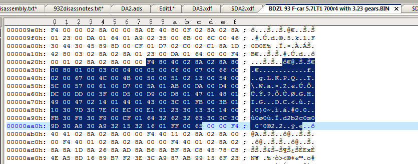
- 1.png (33.29 KiB) Viewed 11147 times
The first occurence is likely going to me mode 1 message 0. From this we know the ALDL RAM buffers are at address $028A, the bytes 02 8A at address 0A16/8A16. It also has the size, $40 or 64 bytes (the ADS specifies 63 payload bytes, not sure why). You would normally start going through the disassembly looking for refrences to 028A but the disassembly txt file has some info that gives a nice shortcut.
It does have an error though, searching for 28A it mentions the buffer is moved to 0x02AD but not during mode 4. Well this is actually done in mode 4 also...
F724 : CMPA #$04
F726 : BNE $F746
F728 : LDD $028B
F72B : STD $02AD
F72E : LDD $028D
F731 : STD $02AF
F734 : LDD $028F
F737 : STD $02B1
F73A : LDD $0291
F73D : STD $02B3
F740 : LDD $0293
F743 : STD $02B5
F746 : LDX $0288
So the mode 4 target AFR gets moved from 293 to 2B5. We know that it was stored in 293 due to counting the frame bytes.
And searching for 02B5 we find...
C6FE : LDAA $02B5
C701 : CLRB
C702 : STD $01AE | M[$01AE] = D
And there is $01AE again so we might be on to something with that one. Checking the Mode 1 Message 0 frame at 0A0F we can look for 01AE. Sadly, after all that it is not there! So either its not included in the frame or we are on the wrong track.
Step two would be to get a data log and see what any undefined bytes do in a data log. Or try logging 01AE to see what it does - can patch the address in the 0A28 message by replacing something else
So thats how I normally find things, use whatever clues you have on hand!