Page 1 of 2
Switch in Hex for Inverted Cam Sensor
Posted: Tue Jul 13, 2021 3:49 am
by RADustin
Gents,
working on getting a non-LS platform up and running. Hoping to bump the key soon, once the DBW plays nicely. For the time being I'll just unplug the cam sensor and batch fire.
It's a P59 PCM, OS 12592618. 24x crank trigger and 1x cam. Coil on plug, no dizzy. Cam and crank sensors are in the timing cover. All waveforms look good, other than the cam high/low, is inverted.
While checking the cam and crank triggers, I noticed the cam sensor is high(12v) while the #1 exhaust valve is in motion and then swaps to low at the next TDC. So basically I believe this to be inverted. It should go high to low after the intake valve closes.
This crank and cam trigger is used on mer cruiser boats, with what looks to be a 512k or 1mb pcm. So I would assume there is a spot in the file that can accept the inverted signal and still get the engine positioning correct. I doubt it's a complete 1 off OS for the boats.
Does anyone have information or any ideas? If there is a mapping to a different OS, I can probably match it up to mine. I have an AVT cable so getting binaries is no problem.
Thank you
-Dustin
Re: Switch in Hex for Inverted Cam Sensor
Posted: Tue Jul 13, 2021 4:26 am
by roughneck427
Post the file. I see a parameter named “Inverted Cam Logic Disabled” and “Cam Inversion Needed”
Re: Switch in Hex for Inverted Cam Sensor
Posted: Tue Jul 13, 2021 5:02 am
by kur4o
Cylinder_At_Cam
The cylinder number present when CAM has just transitionedto the indicated state., Units: Cam_Transition
Current values: [ Min: 0 Max: 8]
rising edge[4.0]
falling edge[1.0]
Does this seems what you need.
Re: Switch in Hex for Inverted Cam Sensor
Posted: Tue Jul 13, 2021 5:39 am
by RADustin
roughneck427 wrote:Post the file. I see a parameter named “Inverted Cam Logic Disabled” and “Cam Inversion Needed”
what OS do you have definitions for? That may work?
Re: Switch in Hex for Inverted Cam Sensor
Posted: Tue Jul 13, 2021 5:48 am
by RADustin
kur4o wrote:Cylinder_At_Cam
The cylinder number present when CAM has just transitionedto the indicated state., Units: Cam_Transition
Current values: [ Min: 0 Max: 8]
rising edge[4.0]
falling edge[1.0]
Does this seems what you need.
I wish it had a little more description.
right now the cam sensor changes state each 360°. I'm using a standard SBC/BBC firing order, so (1-8-4-3)-(6-5-7-2). Basically the PCM knows TDC of #1 on power stroke because the cam will transition low at TDC. If the cam is high at TDC, then #1 is TDC on exhaust stroke and #6 is on power.
I'm not sure why the variables are 4 and 1, and how that lines up. I'll have to think on it more.
Re: Switch in Hex for Inverted Cam Sensor
Posted: Tue Jul 13, 2021 5:50 am
by RADustin
here's a bin of my OS.
Re: Switch in Hex for Inverted Cam Sensor
Posted: Tue Jul 13, 2021 2:25 pm
by roughneck427
I had one act goofy for the cam signal when moved to the timing cover. The oem harness typically has a small jumper harness like on Gen 4 that flips a couple wires. I had to repin the cam sensor not using that jumper. Have you verified the sensor wiring?
Re: Switch in Hex for Inverted Cam Sensor
Posted: Tue Jul 13, 2021 5:02 pm
by delcowizzid
Not to do with your issue but make sure you wire the firing order in the right order you can't just select the firing order in the ecu all the firing order is hard wired and the firing order settings are only for closed loop fueling and missfire detection if you don't change the I jectors wiring around it will fire them at the wrong times to get past the valve. I found this issue doing a bigblock with ls1 loom but was dizzy not coil per plug so you might have to do the same with the coils
Re: Switch in Hex for Inverted Cam Sensor
Posted: Tue Jul 13, 2021 6:41 pm
by kur4o
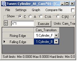
- cam_transition.JPG (17.82 KiB) Viewed 2450 times
This is from l31 engine settings.
I suggest you swap the values to get it right.
Why don`t you start with l31 segment and fix it for cop instead of retune every single table to match the sbc you have. Either case there are tons of ls1 vs sbc table copying.
Re: Switch in Hex for Inverted Cam Sensor
Posted: Tue Jul 13, 2021 10:11 pm
by RADustin
roughneck427 wrote:I had one act goofy for the cam signal when moved to the timing cover. The oem harness typically has a small jumper harness like on Gen 4 that flips a couple wires. I had to repin the cam sensor not using that jumper. Have you verified the sensor wiring?
this has been done. This is where I found the sensor signal was inverted while verifying the triggers.
delcowizzid wrote:Not to do with your issue but make sure you wire the firing order in the right order you can't just select the firing order in the ecu all the firing order is hard wired and the firing order settings are only for closed loop fueling and missfire detection if you don't change the I jectors wiring around it will fire them at the wrong times to get past the valve. I found this issue doing a bigblock with ls1 loom but was dizzy not coil per plug so you might have to do the same with the coils
yes this has all been done. both fixed in the calibration and in the wiring harness.
kur4o wrote:cam_transition.JPG
This is from l31 engine settings.
I suggest you swap the values to get it right.
Why don`t you start with l31 segment and fix it for cop instead of retune every single table to match the sbc you have. Either case there are tons of ls1 vs sbc table copying.
I'm working on a big block. It's a 1MB pcm so no L31 or L21 calibration will work. The base file is all made up, and I've done a few of these already so I'm sure it will run as-is...the difference being no dizzy(at all, internal oil pump drive) and cam sensor under the timing cover.
I'm sure that a tuning solution exists. I just rather fix it in calibration rather than make some additional hardware to flip the signal.