Page 1 of 2
Sensor Placement
Posted: Mon Apr 13, 2009 6:22 am
by VNracer34G
Hey guys, i had an idea late the other night, didn't hurt much due to intoxicants

was looking at one of my spare intakes and it strikes me that the AIT sensor is in a dumb place prone to contamination from the injector and combustion chamber and heatsoak from the engine.
Heres the idea
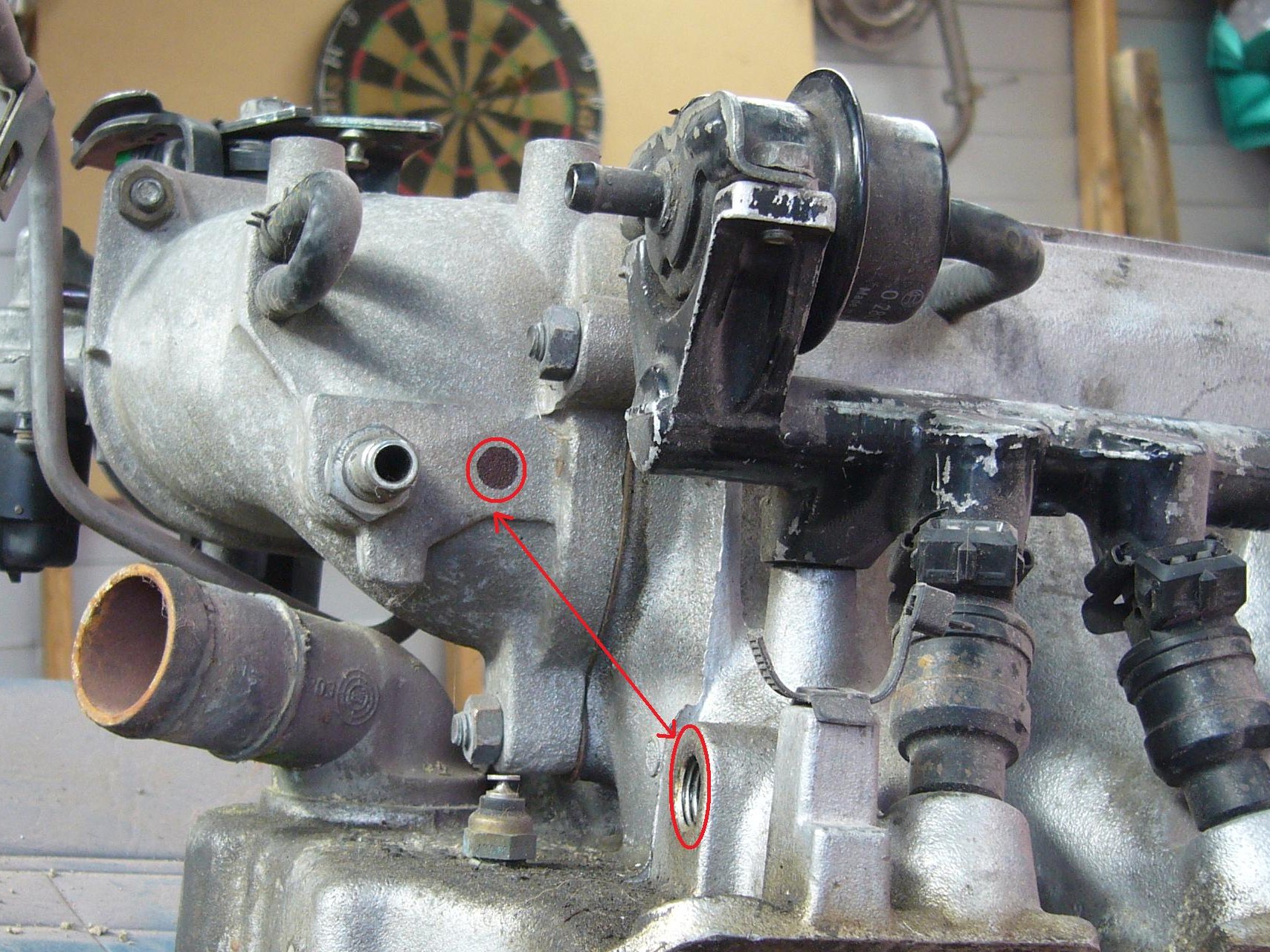
- EASTER09 094.JPG (557.48 KiB) Viewed 7529 times
By moving the AIT sensor to the black dot circled in red it will read fresher air, be less prone to fouling and innacuracy from heatsoak, anyway thats the idea, the plug fits without modifying the loom too.
Seasons over so i cant try it out on the racer for six months and datalogging not allowed anyway, the roadcar/DYNO is a wee while away from re.vinning so input appreciated
delcowizzid as you are not that far down the line from me i'm prepared to send you an elbow tapped out for testing if you wish.....for the good of all
Re: Sensor Placement
Posted: Mon Apr 13, 2009 6:25 am
by VNracer34G
talk about cropping my photo.......damn, its cut off the original hole for AIT sensor but you get the idea
Re: Sensor Placement
Posted: Mon Apr 13, 2009 9:35 am
by Holden202T
i rckon they have put it closer to the inlet port so it gives a more accurate reading of the temperature of the air when its entering the combustion chamber .....
moving it to where you suggest will probably only change the temp a few degrees ...... i guess you can only try hey....
Re: Sensor Placement
Posted: Mon Apr 13, 2009 9:44 am
by monaro308
Hi VNracer,
On the V8's the MAT sensor is located between injectors 6 and 8 (i think)haven't looked for awhile.
The ideal spot thats recommended is closest to the cylinder even though there is heat soak.
I guess it's better to read the air temp right at entry of the intake port/s.
Mat sensors have a brass base to control heatsoak.
Where as if you are talking about the IAT (intake air temp) i think they started in the ecotec,these had plastic bases due to being fitted in the airbox.
I think this worked in tandem with the MAF sensor so VE values would be different.
Do a google on IAT and MAP sensor placements....it's enough to make you go nuts and then wonder why GM spends billions on R & D.
Sometimes/most times it's better the devil you know.
Re: Sensor Placement
Posted: Mon Apr 13, 2009 11:51 am
by VNracer34G
Cheers guys. methinks me thinks too much

Re: Sensor Placement
Posted: Mon Apr 13, 2009 4:48 pm
by delcowizzid
I would remove it completely from the intake manifold and put it in the plastic intake pipe if you still run one.it takes ages for the sensor to cool back down after you have been sitting in traffic or been staging at the drags and the engine can run leaner till the sensor cools down again.its pretty much another coolant temp sensor where its mounted now from so much heat soak.when fitting free flow filter and CAI it is suggested to move it too the intake pipe and when boosting as well as it reacts much faster to changes in air temp.just drill a hole in the intake pipe for it to screw into then seal it with some O2 sensor safe sealant after its screwed in and extend the wires to reach it or un-wrap them from the harnes till they reach and tape it back up.
Re: Sensor Placement
Posted: Mon Apr 13, 2009 8:00 pm
by antus
Looking at the sensor, the bit that does the actual measurement is on thin wire, away from the screw in portion of the sensor, so i'd imagine that its temp would be pretty close to that of the air flowing through it. Even if the base had warmed up, only so much heat can flow out to the measuring part. Then there is also the fact the temp corrections would be calibrated for the existing location, so even if you could move it to a better spot you'd need to re-map those tables to suit.

- MAT_Sensor_6238.JPG (121.26 KiB) Viewed 7480 times
Re: Sensor Placement
Posted: Mon Apr 13, 2009 9:24 pm
by delcowizzid
yeah its the cheats way to richen the tune in the ecu too moving it LOL but it does help a lot my logs the IAT sensor matches my coolant temp when cruising and it takes a fair while at WOT to bring it back down colder surely the air in the intake is getting sucked in fast enough to not warm up too coolant temperature.all the later models have the sensor elsewhere now too must have clicked on.i wonder if that sensor element is sensitive enough to sense the radiant heat from the brass cage around it.mind you those little wires would transfer a lot of heat ever held a resistor while soldering it ouch really fast LOL
Re: Sensor Placement
Posted: Mon Apr 13, 2009 11:16 pm
by VL400
Personally i would not move it out into the intake track too far. The MAP based systems are a speed density system. The ECM trys to calculate the air density to know how much fuel to inject to achieve the target AFR at the given RPM (Speed). For the air temp component it works out the inverse air temp term which is from a lookup table that uses charge air temp as the offset. The charge air temp term uses the coolant temp to try and account for heat soak and the manifold heating the air on its way to the cylinder. Its all fairly involved and there are a few few tables to change to get it to work as just air temperature.
Here is the calculation for determinig charge air temp....
Charge Temp = (CTS * %CTS Cont) + (MAT / %CTS Cont)
Which is part of the over all pulse width calc....
BPW = BPC*T*A/F*VE*BAT*BLM*DFCO*DE*CLT*LSE*EGR
Where: (everything labeled "term" is from a lookup table)
BPW = Inj pulse width in milliseconds
BPC = KINJFLOW term, Displacement/inj flow rate (Litres/Grams per sec) (0-100% BPW Reduction)
T = Inverse Temp Term (Lookup Based On Charge Temp) (0-100% BPW Reduction)
A/F = Inverse air/fuel ratio term
VE = volumetric efficiency term (0-100% BPW Reduction)
BAT = Battery voltage compensation term (+-50% BPW Correction)
BLM = Block Learn Term (+-50% BPW Correction)
DFCO= Decel Fuel Cutoff Term (0-100% BPW Reduction)
DE = Decel enleanment term (0-100% BPW Reduction)
CLT = Closed loop correction (result of O2 sensor Proportional/integral closed loop)(+-50% BPW Correction)
LSE = Low Speed Enrichment Multiplier term (+-50% BPW Correction)
EGR = EGR Dilution term (0-100% BPW Reduction)
Hope that did not muddy the water too much!!
Re: Sensor Placement
Posted: Tue Apr 14, 2009 9:52 am
by antus
yep, good reason not too touch it methinks

Good to know the ecu does compensate for the heatsoak.