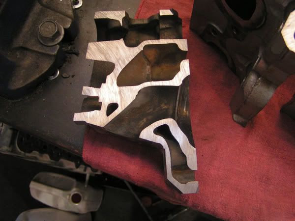
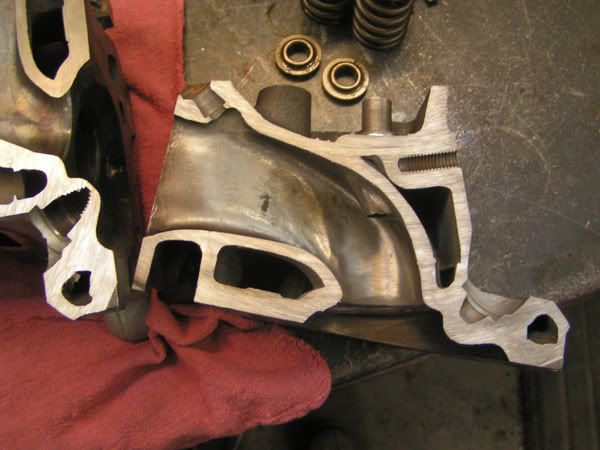
Fins on back of Valve & Fins pre TB

For non EFI mechanical discussion
User avatar
vlad01
Posts: 8550
Joined: Mon Oct 08, 2012 8:41 am
cars: VP I S
VP I executive
VP II executive
VP II executive #2
Location: Kyneton, Vic

Re: Fins on back of Valve & Fins pre TB

Post by vlad01 »

Wall thicknesses of the ports, might you these are already ported.

Image

Image
User avatar
TdracerTd
Posts: 488
Joined: Mon Aug 19, 2013 12:39 pm
cars: Td Gemini coupe (race car WIP)
Holden VE SS ute (tow car/daily)
Vp commodore V6 (race car, s/c, e85, intercooled)
Jeep Grand Cherokee Overland (mrs car, family bus)
My12 subaru STi (Weekend warrior/Toy)
1972 LJ torana GTR (my Dad's car)
Mitsubishi Evo IX

Re: Fins on back of Valve & Fins pre TB

Post by TdracerTd »

Maybe I missed a thread somewhere. What printer are you using. I'm think of getting one myself. I like the look of the rockstock kit.
User avatar
Gareth
Posts: 2678
Joined: Fri Mar 14, 2014 10:37 am
Location: Bacchus Marsh, Vic

Re: Fins on back of Valve & Fins pre TB

Post by Gareth »

Thanks vlad but they are L67 heads...
The1 wrote:you got a design your planning on trying?
Yeah, back on page 13 is the start of a dual runner manifold like the ferrari one vlad posted, i think that this will be the most effective way to make a broader torque band.
According to chemistry, alcohol is a solution...
Dazza92VP
Posts: 608
Joined: Sat Jun 05, 2010 11:59 pm
cars: 92 VP V8 Wagon
Location: Perth

Re: Fins on back of Valve & Fins pre TB

Post by Dazza92VP »

L67 are exactly the same just the injector bosses haven't been drilled on the ecotec ones so all the wall thicknesses and shape will be the same except for the fact that these are ported heads so should be even more meat around then
Looks like some one went a little to deep on the inlet port though
User avatar
The1
Posts: 4852
Joined: Mon Jan 04, 2010 12:23 am

Re: Fins on back of Valve & Fins pre TB

Post by The1 »

Biggvl wrote:Thanks vlad but they are L67 heads...
The1 wrote:you got a design your planning on trying?
Yeah, back on page 13 is the start of a dual runner manifold like the ferrari one vlad posted, i think that this will be the most effective way to make a broader torque band.
missed that, will be interesting. If you go dual plenum that'l have an effect on TIP in to, nothing that can't be taken car of with a tune, top end would like the more volume, then if the runners are a bit long to for more bottom end.
User avatar
The1
Posts: 4852
Joined: Mon Jan 04, 2010 12:23 am

Re: Fins on back of Valve & Fins pre TB

Post by The1 »

TdracerTd wrote:Maybe I missed a thread somewhere. What printer are you using. I'm think of getting one myself. I like the look of the rockstock kit.
That kit doesn't look to bad, has some nice print height to it, the nozzle is 0.5mm not the best now all the new ones are using 0.4mm.

The biggest flaw i see in all these printers is that they are not enclosed, the air temp plays a huge roll in quality of the print. We actually have a few 3D printers at work but ive found the cheapest one the best as it is fully enclosed, though in saying that to make it the best i had to fiddle and calibrate the thing for days to get it running top notch. It's the XYZ Davinci 1.0A, they had a big price drop and most places have them for $700 now, it's print dimensions are 200Lx200Wx200H in mm, it has a 0.4mm nozzle, has a heated bed, can do PLA and ABS, though id rather use ABS, much stronger and can handle more heat. PLA is easier to print with and has less issues with calibration, so if you hear people saying they switched to PLA cause it prints better it usually means they CBF calibrating there printer properly.

The XYZ out of the box is a very good quality printer but locked down so hard you can't do anything with it, it runs a cartridge system so your locked into buying there spool box's, the software allows 0% control over the machine, you can only drop a file in and hit print, in saying that it does work, but no good when you want to do more than print a phone case out. So you use this firmware here with the open source Repetier software host, gives 100% control, you can use whatever slicer you want and setup all the profiles how you want, you can use a spool on the machine as the custom firmware doesn't care about spool cartridges. The firmware mod isn't hard, you can brick the printer but it's not a hard brick, you can clear the firmware by shorting out some pins on startup then just reflash again. I would so love to have one of these at home, the possibilities are endless. Anyway i wont go on to much about it, could be for another thread if there's interest.

http://www.repetier.com/
https://github.com/luc-github/Repetier-Firmware-0.92
User avatar
vlad01
Posts: 8550
Joined: Mon Oct 08, 2012 8:41 am
cars: VP I S
VP I executive
VP II executive
VP II executive #2
Location: Kyneton, Vic

Re: Fins on back of Valve & Fins pre TB

Post by vlad01 »

Biggvl wrote:Thanks vlad but they are L67 heads...
The1 wrote:you got a design your planning on trying?
Yeah, back on page 13 is the start of a dual runner manifold like the ferrari one vlad posted, i think that this will be the most effective way to make a broader torque band.
same heads just injector boss. The page actually shows mostly L36 heads, just the odd L67.

In the states the late L36 and L67 are the same casting just not drilled on the L36.
User avatar
vlad01
Posts: 8550
Joined: Mon Oct 08, 2012 8:41 am
cars: VP I S
VP I executive
VP II executive
VP II executive #2
Location: Kyneton, Vic

Re: Fins on back of Valve & Fins pre TB

Post by vlad01 »

Dazza92VP wrote:L67 are exactly the same just the injector bosses haven't been drilled on the ecotec ones so all the wall thicknesses and shape will be the same except for the fact that these are ported heads so should be even more meat around then
Looks like some one went a little to deep on the inlet port though
Thats the exhaust port (top pic), at the edge of the guide boss. Yeah probably ported too deep there, but that is more or less the shape there.
Dazza92VP
Posts: 608
Joined: Sat Jun 05, 2010 11:59 pm
cars: 92 VP V8 Wagon
Location: Perth

Re: Fins on back of Valve & Fins pre TB

Post by Dazza92VP »

I was looking at the bottom pic he angle the photo was taken at it looked like the valve guide hole is a hole in the inlet wall sort of just didn't look at it right
User avatar
vlad01
Posts: 8550
Joined: Mon Oct 08, 2012 8:41 am
cars: VP I S
VP I executive
VP II executive
VP II executive #2
Location: Kyneton, Vic

Re: Fins on back of Valve & Fins pre TB

Post by vlad01 »

going back tot he bellmouth. Seems to be a bit of question what its for.

my local mechanic mentioned it was to straighten air out due to it favoring one side because of the 90º elbow and that the formula holden engines had overcome this but making an elbow that was vertical.

Was an interesting idea so i went out to test this.

I setup a manifold and intake pipe and supplied an air jet at the beginning of the pipe to form a venturi effect to get some large volume of air moving though.

With bellbouth I found what to be 80% of the air rushing out of both front ports, nearly the remaining from the middle ports and almost undetectable amount from the rear ports.


So out went the bell mouth and results were much different. The 3 driver side ports had heaps of air coming out in equal amounts, pasanger side a little less but virtually the same for the front port, bit less for the middle and not much on the rear but still more than with bellmouth.

I just felt the air bringing my face close to it and feeling it on my skin :lol: so i do my best to describe how it felt. Really it would need some sort of flow meter on each port to get actual numbers.

with bellmouth

L< > R ^F

80%----80%
18%----18%
2%------2%
___| |
_____|

without

18%----20%
14%----20%
8%-----20%
___| |
_____|

Mind you the suction of the engine will over come most of the feed air flow restriction but its extremely interesting to see the difference. When looking into the 2 back ports and half of one middle one you can see its actually blocks most of the port opening in the plenum.

Also I will point out that the 20% figure on the lower diagram flowed like the 80% one up top. So overall the free flowing air increased considerably.