festy's Alfa Romeo Alfetta GTV

Post Your Delco Powered Ride Here
User avatar
festy
Posts: 1039
Joined: Sat Apr 30, 2011 6:27 pm
cars: Alfa Romeos
Location: Narellan, NSW

Re: festy's Alfa Romeo Alfetta GTV

Post by festy »

Looks like you almost lost your camera there at one point :shock:
I tried a similar thing with a webcam years ago after fitting some new springs to my patrol.... maybe a gopro would have lasted longer :oops:
[youtube]https://www.youtube.com/watch?v=aBh9hK4lbXI[/youtube]
User avatar
antus
Site Admin
Posts: 8292
Joined: Sat Feb 28, 2009 8:34 pm
cars: TX Gemini 2L Twincam
TX Gemini SR20 18psi
Datsun 1200 Ute
Subaru Blitzen '06 EZ30 4th gen, 3.0R Spec B
Contact:

Re: festy's Alfa Romeo Alfetta GTV

Post by antus »

Haha yeah good idea, but needs to be rear facing to avoid the mud :)

I was fortunate to have some good advice from people who have tried it before... dont rely on the sucker on bodywork, loop some cable ties through it and the bumper mount as a backup :)
Have you read the FAQ? For lots of information and links to significant threads see here: http://pcmhacking.net/forums/viewtopic.php?f=7&t=1396
User avatar
delcowizzid
Posts: 5499
Joined: Sat Feb 28, 2009 8:38 pm
Location: Wellington NZ
Contact:

Re: festy's Alfa Romeo Alfetta GTV

Post by delcowizzid »

haha love the webcam covered in mud .i cant wait to see this suspension logger would be handy on the starlet logging the launch lift etc
If Its Got Gas Or Ass Count Me In.if it cant be fixed with a hammer you have an electrical problem
User avatar
festy
Posts: 1039
Joined: Sat Apr 30, 2011 6:27 pm
cars: Alfa Romeos
Location: Narellan, NSW

Re: festy's Alfa Romeo Alfetta GTV

Post by festy »

I've been looking for an exhaust flange for the Alfa for a while so I could start making my turbo manifold - but noone seems to sell them so I'd have to make it myself.
There's no way my baby plasma cutter would cut through 10mm plate so I'd either have to mill it which would be slow and a PITA, or draw it up and get a flange laser cut.
Half an hour playing with Qcad gave me a rough idea on how it worked, so I took some measurements of the exhaust ports and came up with this:
Alfetta_Flange1.jpg
Alfetta_Flange1.jpg (17.43 KiB) Viewed 4471 times
I printed it out and it seemed to fit on the engine, so sent the file off.
Much to my surprise, the flange actually fits well! Pretty happy seeing as it's my first attempt at CAD :wtf:
it_fits.jpg
it_fits.jpg (87.28 KiB) Viewed 4471 times
Because the flange bolts to the head on an angle but the exhaust ports exit "straight", the flange ports need to be cut at an angle to save the gasses having to take a sharp corner:
angle_bore1.jpg
angle_bore1.jpg (159 KiB) Viewed 4471 times
angle_bore2.jpg
angle_bore2.jpg (133.94 KiB) Viewed 4471 times
Much better port exit angle:
angle_bore3.jpg
angle_bore3.jpg (87.89 KiB) Viewed 4471 times
User avatar
festy
Posts: 1039
Joined: Sat Apr 30, 2011 6:27 pm
cars: Alfa Romeos
Location: Narellan, NSW

Re: festy's Alfa Romeo Alfetta GTV

Post by festy »

I bought my first arduino recently, and thought my suspension sensor tests might be a good project to cut my teeth on.
With a pair of sensors wired up and a flat object waved around in front of them, this was the result:
2sensors.png
2sensors.png (13.63 KiB) Viewed 4465 times
Then I tried a bit of filtering, taking 3 readings of each sensor and averaging the result:
2sensors_filtered3.png
2sensors_filtered3.png (10.65 KiB) Viewed 4465 times
The filtered readings are a fair bit smoother, but the "noise" in the unfiltered graph is caused by a fluctuation in the readings of about 0.5mm so it's not really a big issue.
I'm not sure what caused the distortion in the filtered graph (red trace around 76-91 on the x axis) - the two sensors were sitting next to each other on my desk so they might have been hearing each other at certain points, I'll get some sensors fitted to my wheel arches and re-evaluate the filtered vs unfiltered results I think.
User avatar
Holden202T
Posts: 10330
Joined: Sat Feb 28, 2009 9:05 pm
Location: Tenambit, NSW
Contact:

Re: festy's Alfa Romeo Alfetta GTV

Post by Holden202T »

turbo manifold flange looks tidy as man!! let the fun begin :)

ditto with the suspension sensors, they should work really well!
User avatar
festy
Posts: 1039
Joined: Sat Apr 30, 2011 6:27 pm
cars: Alfa Romeos
Location: Narellan, NSW

Re: festy's Alfa Romeo Alfetta GTV

Post by festy »

Thanks, I must admit I was a bit nervous while I waited for the flanges to be cut.
I'd ordered a few of them, and was half expecting there to be some stupid little mistake that left me with an expensive pile of scrap metal...
And anyone looking for a decent free CAD program - forget Qcad. Although the community edition is free, it's knobbled and it only supports saving R15 dxf format... which neither the CNC shops I sent it to could open it.
I switched to LibreCAD, which is a fork of Qcad from back when it was really free. So far I'm really happy with it.

Anyway, today's job is running new fuel lines. This morning I ripped out the original hard line and the 5/16 hose I ran parallel to it, and have just finished beating the first new -6 hard line into submission so now I get to try my hand at pipe flaring :?
User avatar
Holden202T
Posts: 10330
Joined: Sat Feb 28, 2009 9:05 pm
Location: Tenambit, NSW
Contact:

Re: festy's Alfa Romeo Alfetta GTV

Post by Holden202T »

from what i've seen you do already, im sure you'll be right with the flaring!!
User avatar
festy
Posts: 1039
Joined: Sat Apr 30, 2011 6:27 pm
cars: Alfa Romeos
Location: Narellan, NSW

Re: festy's Alfa Romeo Alfetta GTV

Post by festy »

First hard line is done.
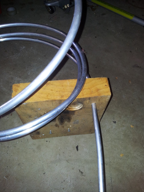
I bought two 12ft rolls of -6 aluminium hard line for the job, first step was to uncoil them so I drilled a 9.5mm hole through a random block of wood and fed the tube through, straightening it out enough for it to go through the hole a bit at a time then pulled it back through the hole for a second pass.
uncoiling.jpg
uncoiling.jpg (176.64 KiB) Viewed 4427 times
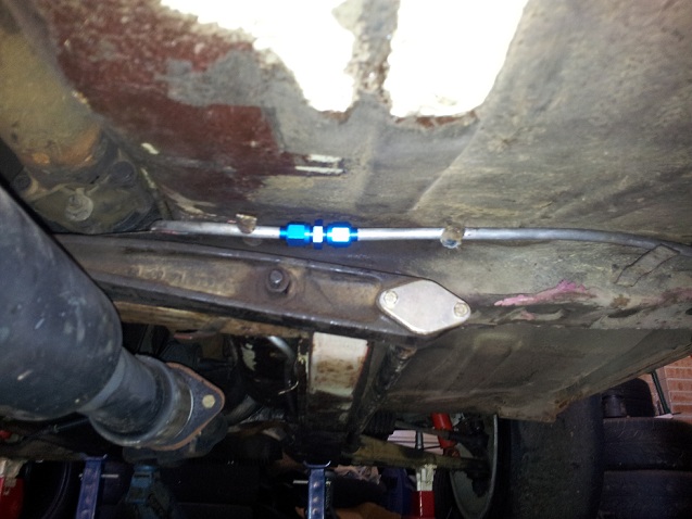
The original fuel line was made in two parts with rubber hose joining them - probably for ease of installation - so I did the same.
Here's my first (and second) flare:
1stflare.jpg
1stflare.jpg (94.7 KiB) Viewed 4427 times
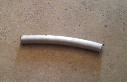
And this is the leftover tube from the first roll, that was close! I could have used that extra at the engine bay end, but oh well :|
leftover.jpg
leftover.jpg (42.23 KiB) Viewed 4427 times
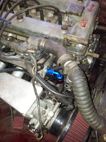
And another new experience for me today, assembling my first braided AN fitting. It was easier than I expected.
Looks a bit out of place in that engine bay though :oops:
fuel_rail.jpg
fuel_rail.jpg (119.6 KiB) Viewed 4427 times
I think the second line might have to be run at least partially through the cabin, because there's really not much room where it passes the tailshaft.
User avatar
festy
Posts: 1039
Joined: Sat Apr 30, 2011 6:27 pm
cars: Alfa Romeos
Location: Narellan, NSW

Re: festy's Alfa Romeo Alfetta GTV

Post by festy »

I was planning on using a GPS module to log road speed, but then I thought maybe I could generate a VSS signal from the GPS which would give me road speed in the logs as well as improve coasting to a stop etc.

It seems pretty easy with an arduino, something like:

Code: Select all

#include <SoftwareSerial.h>
#include <TinyGPS.h>

const int PPK = 1250;
TinyGPS gps;
SoftwareSerial ss(11, 10, true);

void setup()
{
  ss.begin(4800);
}

void loop()
{
  // pulses per second = km/s * ppk
  // and km/s = km/h / (60 * 60)
  int freq = (gps.f_speed_kmph() * PPK) / 3600;
  tone(12,freq);
  delay(200);
}
I haven't got as far as feeding the signal into an ECU yet, but the generated pulse at least looks like what I would expect to see (during accelleration here):
ppk.png
ppk.png (4.02 KiB) Viewed 4409 times
Any obvious reason why this wouldn't work? It seems almost too easy...
Post Reply