I preferable dont want to have to use header files.. so compiling into one file will be what Ill be looking to do.
So theres 4 main files to look at here:
J1850.h
J1850.c
Main.h
Main.c
Might as well start with the VPW protocol controlling files, so opening up J1850.h file: (All credits to Michael wolf!)
Code: Select all
#ifndef __J1850_H__
#define __J1850_H__

/*** CONFIG START ***/

#define J1850_PORT_OUT	PORTC	// J1850 output port
#define J1850_DIR_OUT 	DDRC	// J1850 direction register
#define J1850_PIN_OUT		3			// J1850 output pin

#define J1850_PORT_IN		PINC	// J1850 input port
#define J1850_PULLUP_IN	PORTC	// J1850 pull-up register
#define J1850_DIR_IN 		DDRC	// J1850 direction register
#define J1850_PIN_IN		0			// J1850 input pin

#define	J1850_PIN_OUT_NEG			// define output level inverted by hardware
#define	J1850_PIN_IN_NEG			// define input level inverted by hardware

/*** CONFIG END ***/

#ifdef J1850_PIN_OUT_NEG
	#define j1850_active() J1850_PORT_OUT &=~ _BV(J1850_PIN_OUT)
	#define j1850_passive() J1850_PORT_OUT |= _BV(J1850_PIN_OUT)
#else
	#define j1850_active() J1850_PORT_OUT |= _BV(J1850_PIN_OUT)
	#define j1850_passive() J1850_PORT_OUT &=~ _BV(J1850_PIN_OUT)
#endif

#ifdef J1850_PIN_IN_NEG
#define is_j1850_active() bit_is_clear(J1850_PORT_IN, J1850_PIN_IN)
#else
#define is_j1850_active() bit_is_set(J1850_PORT_IN, J1850_PIN_IN)
#endif

/* Define Timer1 Prescaler here */
#define c_start_pulse_timer	0x01  // Timer1 runs without Prescaler, 135ns tick @ 7,3728MHz
#define c_stop_pulse_timer	0x00


// define error return codes
#define J1850_RETURN_CODE_UNKNOWN    0
#define J1850_RETURN_CODE_OK         1
#define J1850_RETURN_CODE_BUS_BUSY   2
#define J1850_RETURN_CODE_BUS_ERROR  3
#define J1850_RETURN_CODE_DATA_ERROR 4
#define J1850_RETURN_CODE_NO_DATA    5
#define J1850_RETURN_CODE_DATA       6

// convert microseconds to counter values
#define us2cnt(us) ((unsigned int)((unsigned long)(us) / (1000000L / (float)((unsigned long)MCU_XTAL / 1L))))

#define WAIT_100us	us2cnt(100)		// 100us, used to count 100ms

// define J1850 VPW timing requirements in accordance with SAE J1850 standard
// all pulse width times in us
// transmitting pulse width
#define TX_SHORT	us2cnt(64)		// Short pulse nominal time
#define TX_LONG		us2cnt(128)		// Long pulse nominal time
#define TX_SOF		us2cnt(200)		// Start Of Frame nominal time
#define TX_EOD		us2cnt(200)		// End Of Data nominal time
#define TX_EOF		us2cnt(280)		// End Of Frame nominal time
#define TX_BRK		us2cnt(300)		// Break nominal time
#define TX_IFS		us2cnt(300)		// Inter Frame Separation nominal time

// see SAE J1850 chapter 6.6.2.5 for preferred use of In Frame Respond/Normalization pulse
#define TX_IFR_SHORT_CRC	us2cnt(64)	// short In Frame Respond, IFR contain CRC
#define TX_IFR_LONG_NOCRC us2cnt(128)	// long In Frame Respond, IFR contain no CRC

// receiving pulse width
#define RX_SHORT_MIN	us2cnt(34)	// minimum short pulse time
#define RX_SHORT_MAX	us2cnt(96)	// maximum short pulse time
#define RX_LONG_MIN		us2cnt(96)	// minimum long pulse time
#define RX_LONG_MAX		us2cnt(163)	// maximum long pulse time
#define RX_SOF_MIN		us2cnt(163)	// minimum start of frame time
#define RX_SOF_MAX		us2cnt(239)	// maximum start of frame time
#define RX_EOD_MIN		us2cnt(163)	// minimum end of data time
#define RX_EOD_MAX		us2cnt(239)	// maximum end of data time
#define RX_EOF_MIN		us2cnt(239)	// minimum end of frame time, ends at minimum IFS
#define RX_BRK_MIN		us2cnt(239)	// minimum break time
#define RX_IFS_MIN		us2cnt(280)	// minimum inter frame separation time, ends at next SOF

// see chapter 6.6.2.5 for preferred use of In Frame Respond/Normalization pulse
#define RX_IFR_SHORT_MIN	us2cnt(34)		// minimum short in frame respond pulse time
#define RX_IFR_SHORT_MAX	us2cnt(96)		// maximum short in frame respond pulse time
#define RX_IFR_LONG_MIN		us2cnt(96)		// minimum long in frame respond pulse time
#define RX_IFR_LONG_MAX		us2cnt(163)		// maximum long in frame respond pulse time

uint8_t timeout_multiplier;  // default 4ms timeout multiplier

extern void j1850_init(void);
extern uint8_t j1850_recv_msg(uint8_t *msg_buf );
extern uint8_t j1850_send_msg(uint8_t *msg_buf, int8_t nbytes);
extern uint8_t j1850_crc(uint8_t *msg_buf, int8_t nbytes);

static inline void timer1_ctrl(uint8_t val)
{
    TCCR1B = val;
}

static inline void timer1_start(void)
{
    TCCR1B = c_start_pulse_timer;
    TCNT1 = 0;
}

static inline void timer1_stop(void)
{
    TCCR1B = c_stop_pulse_timer;
}

static inline void timer1_set(uint16_t val)
{
    TCNT1 = val;
}

#endif // __J1850_H__
Starting with the top: (PORTx = if it should be high or low, DDRx = if input or output, PINx = pin on MCU)
#define J1850_PORT_OUT PORTC // J1850 output port -
var PORT_OUT is PORTC, used to set pin as high or low
#define J1850_DIR_OUT DDRC // J1850 direction register -
var DIR_OUT is DDRC, used to set direction.. eg input or Output
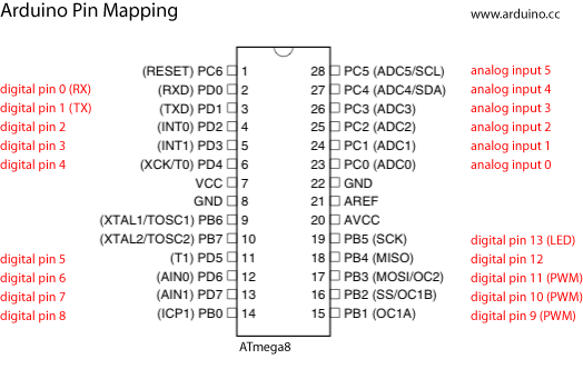
#define J1850_PIN_OUT 3 // J1850 output pin -
var PIN_OUT is set to pin 3...is connected to OBD2 Connector same as Analogue input 3 on Arduino
#define J1850_PORT_IN PINC // J1850 input port -
var PORT_IN is PINc, used to set the pin on MCU (bit confused)
#define J1850_PULLUP_IN PORTC // J1850 pull-up register -
var PULLUP_IN is PORTC, used to set pin as high or low
#define J1850_DIR_IN DDRC // J1850 direction register -
var DIR_IN is DDRC, used to set direction eg Input or Output
#define J1850_PIN_IN 0 // J1850 input pin -
var PIN_IN is set to 0..is connected to OBD2 Connector same as Analogue input 0 on Arduino
#define J1850_PIN_OUT_NEG // define output level inverted by hardware
- Wont need to be inverted since not serial port
#define J1850_PIN_IN_NEG // define input level inverted by hardware
- Wont need to b inverted since no serial port
I think thats the setup for the vpw pins. So its equivalent to setting the pins as High/low, Out/In and setting the actual pin. The defined variables will be called and set throughout the program to the required values. (If anyone has any comments, now wold be great!)