When i first started thinking about putting an 0411 pcm on a 6 cylinder i knew i needed to work out a crank trigger (easy, plenty of options out there) and a cam trigger, which for a straight 6 is less common.
my searches for this showed up ford taurus and falcons as some examples of dizzy cars adapted which used something like this.

- s-l1600.jpg (41.16 KiB) Viewed 4531 times
this led me to find the right sensor for them and it looked like something i could easily adapt to a electronic dizzy housing, and the sensor was $30 delivered so not too much cost if it didn't work out.
so i found an old fucked dizzy and stripped all the shit out of it to leave the body, main shaft and the reluctor mounting plate.
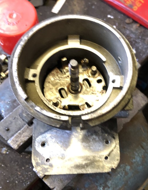
- IMG_0346.JPG (84.47 KiB) Viewed 4531 times

- IMG_0347.JPG (128.45 KiB) Viewed 4531 times
i then mapped out the sensor and the plate in autocad to make a template to lay over the plate to mark for hole drilling.
you can see a second line that doesn't go through the holes, that is the centre line of the sensor bolt holes.

- IMG_0426.JPG (74.78 KiB) Viewed 4531 times
This template will also alow a new piece to be cut from steel if someone so desired.
The sensor mounted to the plate, and the hole in the plate has been reamed out to just allow the sensor edge to be level but still keeping some meat for the screws.
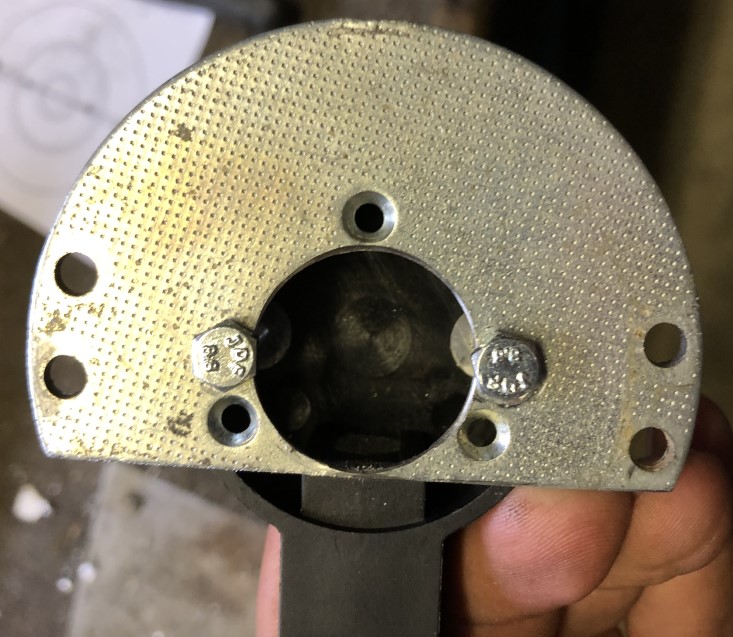
- IMG_0433.JPG (125.67 KiB) Viewed 4531 times
I then trimmed the housing hole a bit wider to fit the sensor through, it needs some cleaning up but that can happen after it works

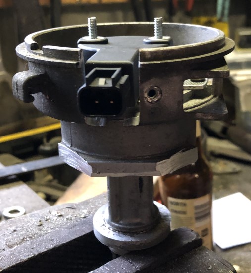
- IMG_0435.JPG (65.92 KiB) Viewed 4531 times

- IMG_0436.JPG (139.15 KiB) Viewed 4531 times
Whats left to do now is to modify the old advance part of the shaft which should work nicely as a chopper wheel for it.
i had originally planned to make it a 50/50 on/0ff sensor for the 0411 pcm, but with it looking like that might not be much of an option at the moment on a 6 cylinder i have decided to just make it a 1 notch sensor for use with anything, once its finished i'll probably use a VL400 igntion module to bench test it and see what the trace looks like from it on the drill.
after doing this i have some thoughts for revisions.
firstly im not sure if its just the sensor i bought, but it has threaded holes in the sensor, i would probably drill these out and have the thread in the base plate, but having said that, the exposed threads might be useful to make a 3d printed cap or even alloy and retain it with the two screw ends.
on the above theory i would probably make a plate from scratch out of 5mm plate and tap threads into it, and also it really needs some crush tubes for longevity.
if anyone is interested in this, here is the autocad file.

- dizzy plate.jpg (45.08 KiB) Viewed 4531 times
i printed it at 1:1 scale and it was exact to my needs.