Page 2 of 2
Re: PCM Logger test simulation
Posted: Fri Aug 13, 2021 10:45 pm
by delcowizzid
I have tps map coolant and iat all on trim pots for testing 808s
Re: PCM Logger test simulation
Posted: Fri Aug 13, 2021 10:47 pm
by delcowizzid
I also used a maf ecu on my head flow bench the maf wouldn't read without crank a working trigger input so if you are testing code you may need to rig some form of signal generator up
Re: PCM Logger test simulation
Posted: Sat Aug 14, 2021 2:00 am
by Gampy
Unable to find a 10k, will this get the job done ??
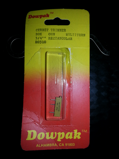
- 20kTrimmer.png (339.5 KiB) Viewed 3074 times
I know I have some 10k's, I'll have to wait until someone is around to help me, maybe tomorrow.
Thanks!
-Enjoy
Re: PCM Logger test simulation
Posted: Sat Aug 14, 2021 2:15 am
by turbo_v6
Yeah I think that should still work.
Re: PCM Logger test simulation
Posted: Sat Aug 14, 2021 3:40 am
by Gampy
Thank ya sir!
Is IAT also 0-5v, I have a piles of temperature sensors like Analog Devices AD22100 (as well as other MFG ones).
Re: PCM Logger test simulation
Posted: Sat Aug 14, 2021 6:28 am
by MudDuck514
Hi all;
Gampy, if you were to connect the 5v supply to the wiper arm of the potentiometer (Center pin) once the arm got close to the grounded pin the potentiometer would start smoking. NOT good!
As for the exact value you use, it doesn't matter what the value is as long as it is high enough to NOT present a high current draw (see above). All that will happen is the lower value control will be more sensitive to adjustment -
use the 20k if you need more precision than the 10k provides, though again, all you are needing is a set value that doesn't change all the time.
Mike
Re: PCM Logger test simulation
Posted: Sat Aug 14, 2021 7:17 am
by Gampy
That's right, I just need a known value in the PCM, so I know if the Logger is getting the right value.
Thank ya sir!
Re: PCM Logger test simulation
Posted: Sat Aug 14, 2021 9:03 am
by Gampy
Well, I'd say I taught that pot to smoke on a previous occasion ...
So, I hooked up a mini micro switch between C1-P8 and C2-P24, it definitely shows up in Logger when I hit the button.
Now Logger is throwing an OutOfMemoryException ... Not sure why yet, or if the two are related.
Re: PCM Logger test simulation
Posted: Sun Aug 15, 2021 8:25 pm
by Gampy
So, this is what I did and the results of doing so ...
I used a mini micro switch that has three pins, Common, Normally Open, Normally Closed and hooked it up like so,
Common ----------> C2 - Pin 24: TPS Sensor Signal
Normally Open ---> C1 - Pin 8: +5 Volt Ref
Normally Closed --> C1 - Pin 60: Low Ref
You do need to go both ways, if you just do
C1 - Pin 8: +5 Volt Ref ---> C2 - Pin 24: TPS Sensor Signal
as I first did, it causes all sorts of havoc, I believe the PCM crashes (resets), causing the Tool (MDI in this case) to crash, causing PCM Logger to crash!
After I did the three way Micro hookup it's worked flawless ...
My PCM Logger entries.
Parameters.RAM,
Code: Select all
  <RamParameter
    id="RamTPS"
    name="TPSinRAM"
    description="10 bit RAM Throttle Position Sensor"
    storageType="uint16"
    bitMapped="False">
    <Location os="12216125" address="0xFFF2FC" />
    <Location os="12587603" address="0xFFF2FC" />
    <Conversion units="Volts" expression="x" format="0.00" />
    <Conversion units="Raw" expression="x" format="0.00" />
  </RamParameter>
LogProfile,
Code: Select all
    <RamParameters>
        <Unused-RamParameter id="RamTPS" units="Volts" />
        <RamParameter id="RamTPS" units="Raw" />
    </RamParameters>
Results,
C1 - Pin 60: Low Ref --> C2 - Pin 24: TPS Sensor Signal (Button NOT pushed),

- TPS-Testing_TPStoGND.png (26.33 KiB) Viewed 3016 times
And,
C1 - Pin 8: +5 Volt Ref --> C2 - Pin 24: TPS Sensor Signal (Button Pushed),
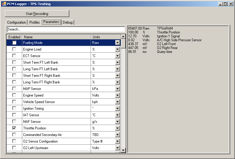
- TPS-Testing_TPSto+5v.png (26.37 KiB) Viewed 3016 times
Thank y'all for your help!
What would the conversion expression be ??
-Enjoy