Well as you know I took delivery of a JAW (Just Another Wideband) wideband controller and display today from Alan at
http://www.14point7.com for some development and testing and to give it an impartial reveiw.I wasnt even expecting it to arrive yet i didnt even know it was on its way yet.then yesterday I got a notice in the mail that i had a parcel to pick up as it wouldnt fit in the mailbox.so i grabbed someones pushy and off to the mail delivery centre I went and low and behold a package from Canada woooo I know what that is I thought couldnt wait to get home and assemble it.about 20 metres from the post office the chain snapped on the bike noooooo now i have to walk home which is wasting valuable time

anyway finally made it home and opened my parcel.
inside was 2 cuircuit boards of nice quality which were fully silk screened and coated with protective sealant very nice for when it comes time to solder as i found with VL400's boards the solder doesnt cross tracks and only pools where it is meant too.also in the package was all the required resistors capacitors chips and connections etc.
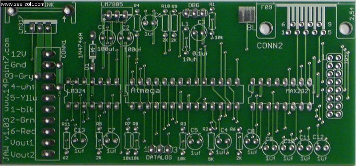
- jawboardmain.jpg (65.61 KiB) Viewed 7938 times
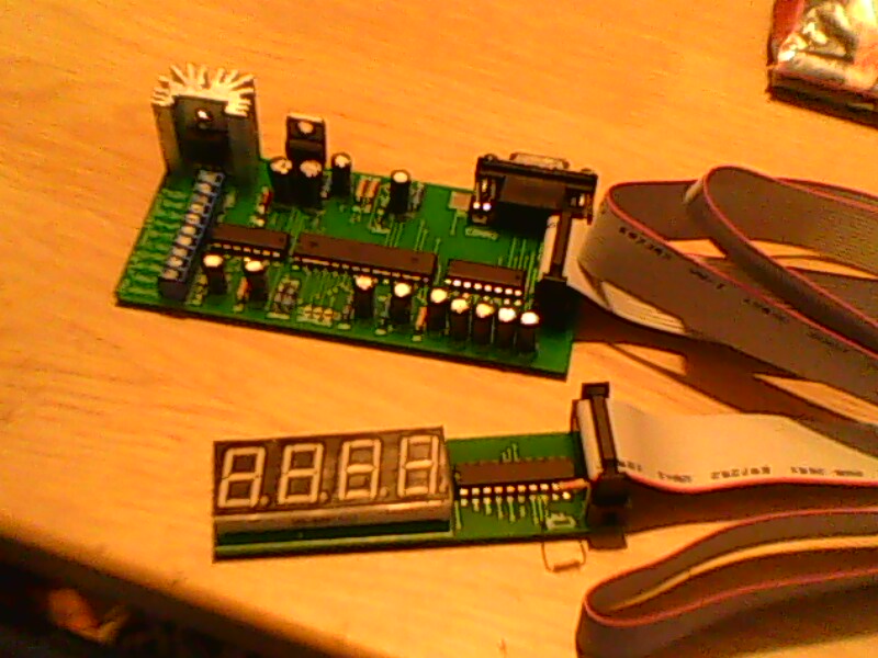
by the time it was unpacked the iron was allready hot ready to go so i got stuck in.resistors and diode first as the instructions off the website said this was a quick task.next were the max232 and the other small chip soldered one side lot of pins at a time being carefull not to heat the chip and checking temp between pins and letting it cool if required.then the atmel went in the most important one as you cant just duck down the shop and get one as the boot loader needs to be programmed on before it goes in and being that i dont have a copy of that i was being extra carefull with this one .all went in no worries making sure it stayed cool in the process.soldered in the connector for the display and for the sensor and the serial connection easy as .the only thing i can think that would be a nice addition would be some pads to solder the serial port retainers too on the circuit board as they are just pushed through the holes in the board and most of the strain will be on the pins but it is secured in there well anyway.slapped in the caps and the 2 regs and heat sink and she was done.
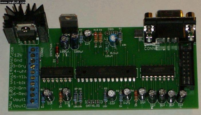
- jawboardass.jpg (52.44 KiB) Viewed 7940 times
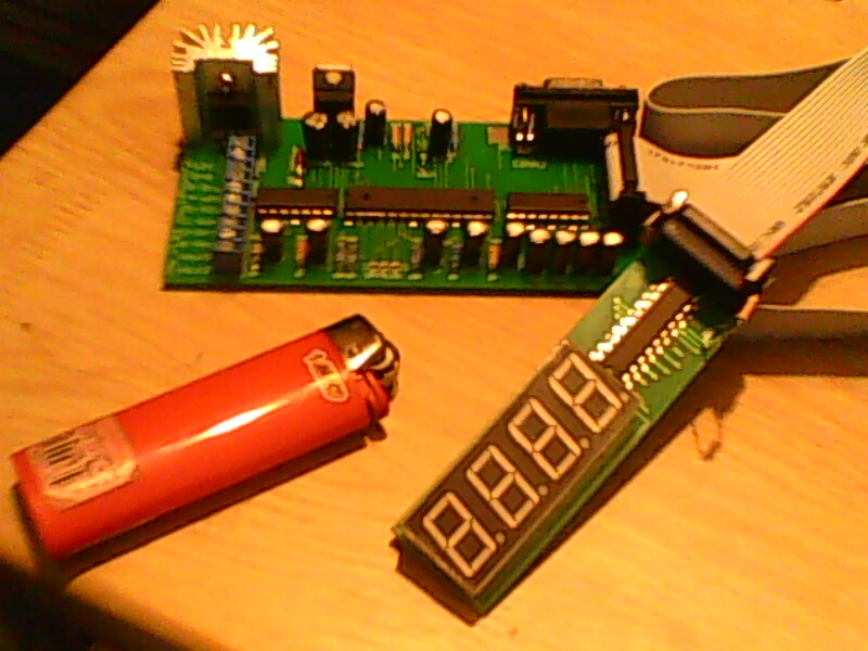
the display took another few minutes to do. all up took about 30mins .allow an hour max for a steady reliable job it needs good solder joints if you want it to work good and reliable. no dry joints here all look nice and wet just what you want.so i dragged out my testbench power supply after making a coffee crossed my fingers and powered it up for a test with no sensor .low and behold worked first time nice bright screen with a resistor slot which you can change the resister value if you want brighter or dimmer.
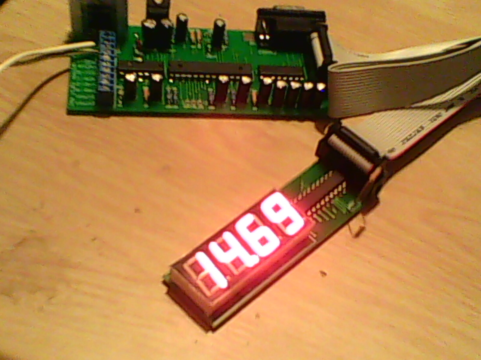
- IMG0084A.jpg (317.29 KiB) Viewed 7939 times
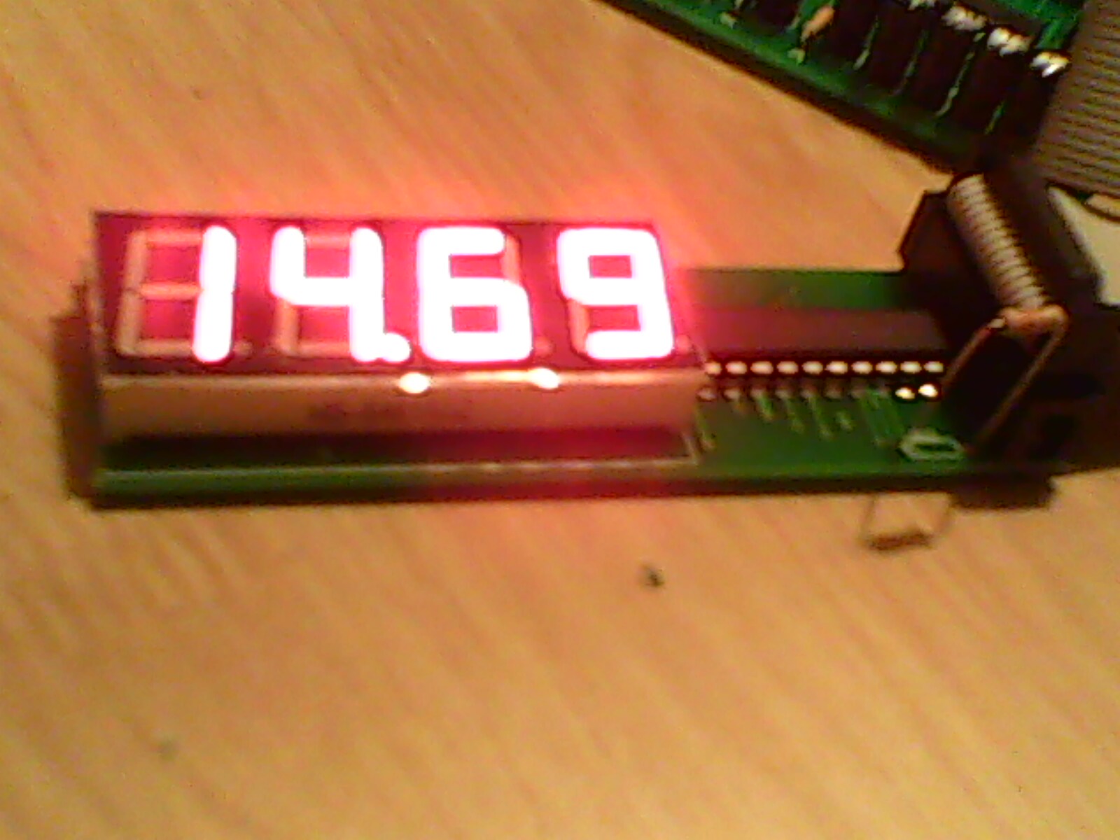
- IMG0085A.jpg (271.7 KiB) Viewed 7936 times
I have allready blown the Zener diode by accedent by an accedental reverse polarity but i just removed it till i can get a replacement and its all still working i was a bit worried for a few minutes that my new toy/tool had lasted no more than a few minutes since completion but a quick search on the JAW forum soon pointed me in the right direction as to why it wasnt going due to the protection diode so all is well.great resorce the forum has a list of know compatable sensors and usb>serial cables.and many other topics to help with any issues.but lots of whingers who most likely stuffed up there assembly.
as i stand now I feel it is a great unit at a great price sure the regulator might get a bit hot when i get a sensor in there but thats no worry to me even if the sensor only kast 5 tunes on 5 cars ill be happy enough but im sure it should last a while if taken care off.I dont really plan on it being a continuously mounted every day replacement for the narrowband only as a tuning tool so should last for ages.cant wait to get a sensor and get this thing going properly and test its accuracy and refresh rate.
I poached one of alans picks of a completed unit and display im sure he wont mind just my camera is shite most of the other pics are my phone camera cause its better than the digital camera i have.
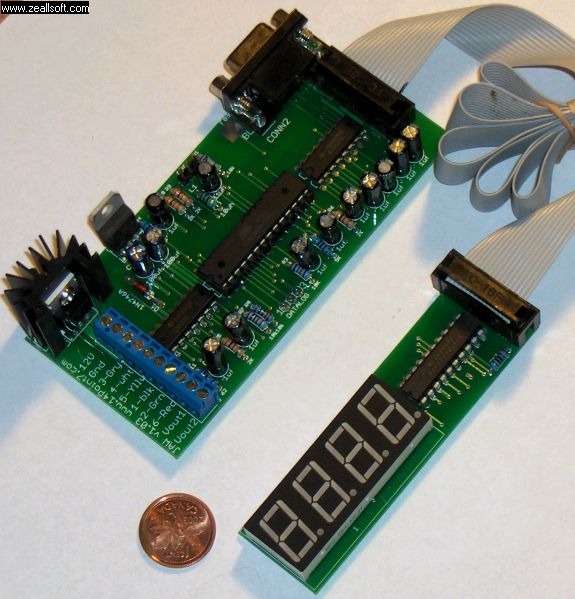
- jawboards al.jpg (63.29 KiB) Viewed 7934 times
now the software after battling for over 3 hours to get my PC to be freinds with microsofts .net 2.0 redistributable package
bloody microsoft i do blame the slow as old PC as well its well past its useby date.but i finally got it all going started the software plugged in with my cheap prolific usb>serial cable hit get firmware and away she went ready to go i havnt bothered to try flashing any firmware updates as yet as it works as is and why mess with something thats allready going so far.ill be doing some more researce into the firmware revisions before i go flashing one in yet.
software pics OK heres one
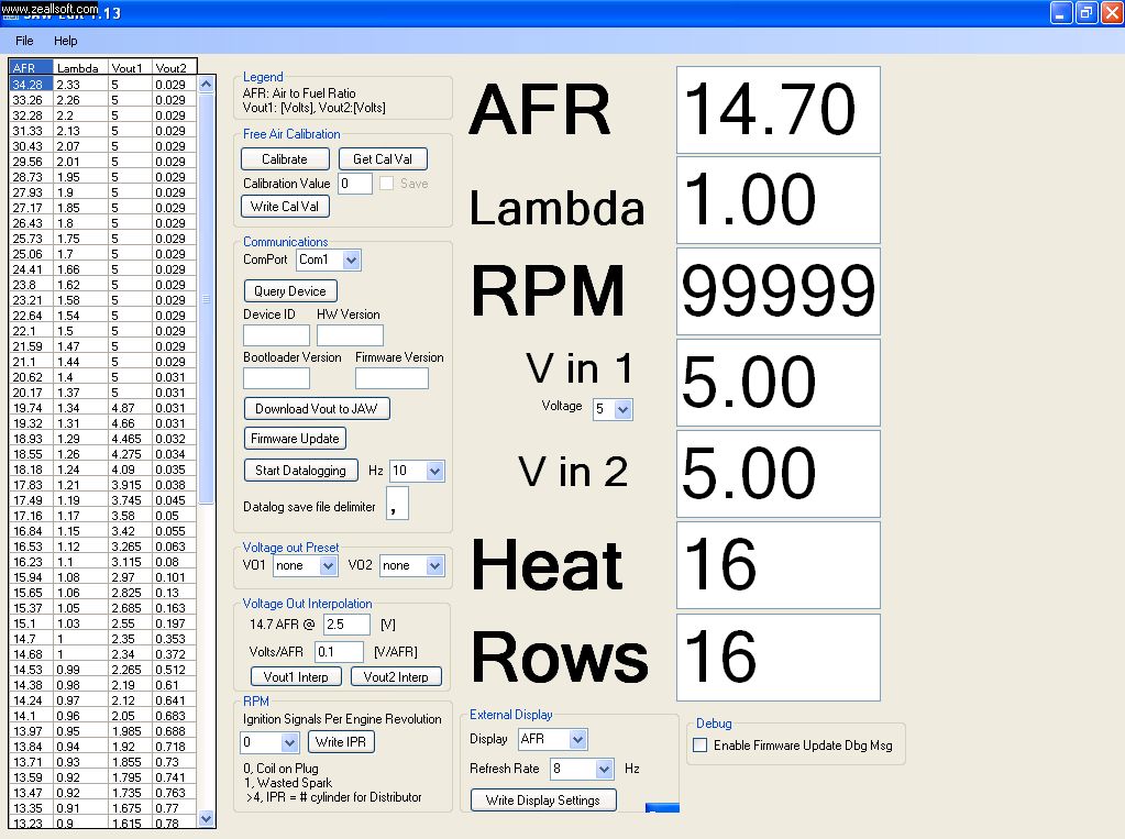
- jawsoft.jpg (161.6 KiB) Viewed 7936 times
later versions of the software have a different setup but very similar but you can detach the seperate windows and maximise the ones you want but im happy with what i have for the next few days.will get back over on there forum for a refresher coarse in the jaw software its been a fair few months since i was last over there.
features include
1x wideband sensor input ,
1x RPM input upto some crazy amount of revs ill never get up to,
2 x 0-5 volt inputs MAP volts etc
1x serial output to laptop
1x external remote display
2x programmable outputs for narrowband simulation and if VL400 works some magic hopefully a 0-5 volt o2 input to the ecu to be displayed in ALDL logs and on screen on scannerpro while tuning

.
right a pic or 2 more and my novel is over for now till i get my sensor here.
- IMG0082A.jpg (109.12 KiB) Viewed 7927 times
- IMG0079A.jpg (110.32 KiB) Viewed 7924 times
i still have to make a box for the unit and a seperate one for the display too but i might go see what dicksmiths or jaycar have on off for some hacking of probably install a fan or pc processor radiator setup on the heatsink as well.and make a nice little display case fir easy mounting in the car it comes with an 85cm ribbon cable so plenty of length there too.


